Measuring Arrangement for Brake Application Force Measurement of a Disc Brake and a Corresponding Disc Brake

Active Publication Date: 2015-01-29
KNORR-BREMSE SYST FUER NUTZFAHRZEUGE GMBH
View PDF26 Cites 5 Cited by
  • Summary
  • Abstract
  • Description
  • Claims
  • Application Information

AI Technical Summary

Benefits of technology

[0025]A cable combination of the sensor cable and of a wear sensor cable is also possible, and this in turn reduces installation expenditure and installation space. The sensor cable can, of course, also be connected directly to a brake control unit.
[0026]The housing can easily be attached to one of the components and/or to a base plate of the disc brake in a simple manner by use of at least one attachment element directly and/or via at least one clip. For the purpose of rapid mounting and dismounting, the housing can also be screwed.
[0027]The measurement object can be embodied as a brake pad holding bracket which can be permanently connected to the one of the two components of the disc brake, in particular to the caliper back and which has the at least one end face or the at least one target object with at least one end face. The target object can be connectable directly to the brake pad holding bracket, directly or via a holding element. In this way, the target object, which is metallic or has a metallic element, can be screwed on, riveted on, welded on or joined on in some other way. It can be embodied in one piece with the pad holding bracket. Of course, the pad holding bracket can have more than one metallic element or more than one target object. As a result of the fact that the measuring arrangement is partially arranged on the pad holding bracket, or the pad holding bracket is part of the measuring arrangement, simple replacement possibilities during maintenance and servicing of the brake are obtained. Retrofitting of a brake around the measuring arrangement is also simplified.
[0028]In order to increase the measuring accuracy, the pad holding bracket can be attachable with a centering device to the one component. Nevertheless, the pad holding bracket can be r

Problems solved by technology

However, a disc brake on a vehicle is subjected to relatively extreme operating conditions which can influence in different ways a measurement variable which correlates with the brake application force of the disc brake.
Although this measuring arrangement has proven effective in practice, malfunctions can occur if contamination or other particles, which no longer permit contactless measurement, accumulate between the brake application force sensor and the measurement object or the target object section thereof.
In such cases, the contamination or the other particles bring about a risk of contact between the brake application force sensor and the measurement object or the target object section thereof which are displaced with respect to one another.
The same

Method used


Image

  • Measuring Arrangement for Brake Application Force Measurement of a Disc Brake and a Corresponding Disc Brake
  • Measuring Arrangement for Brake Application Force Measurement of a Disc Brake and a Corresponding Disc Brake
  • Measuring Arrangement for Brake Application Force Measurement of a Disc Brake and a Corresponding Disc Brake

Examples


Example

DETAILED DESCRIPTION OF THE DRAWINGS

[0041]Identical components or functional units with the same function are characterized by the same reference symbols in the figures.

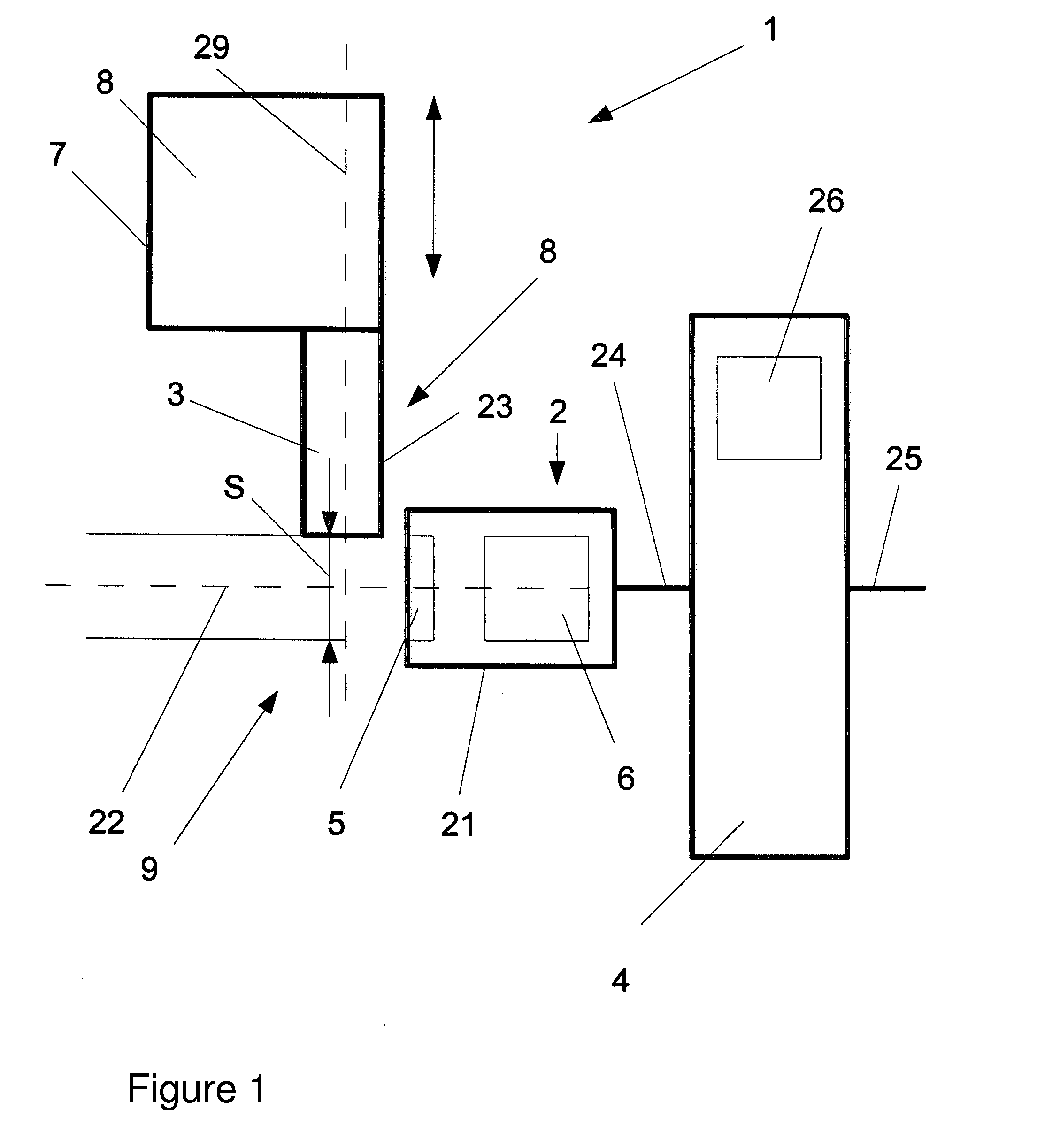
[0042]FIG. 1 shows a schematic block illustration of a first exemplary embodiment of a measuring arrangement 1 according to the invention.

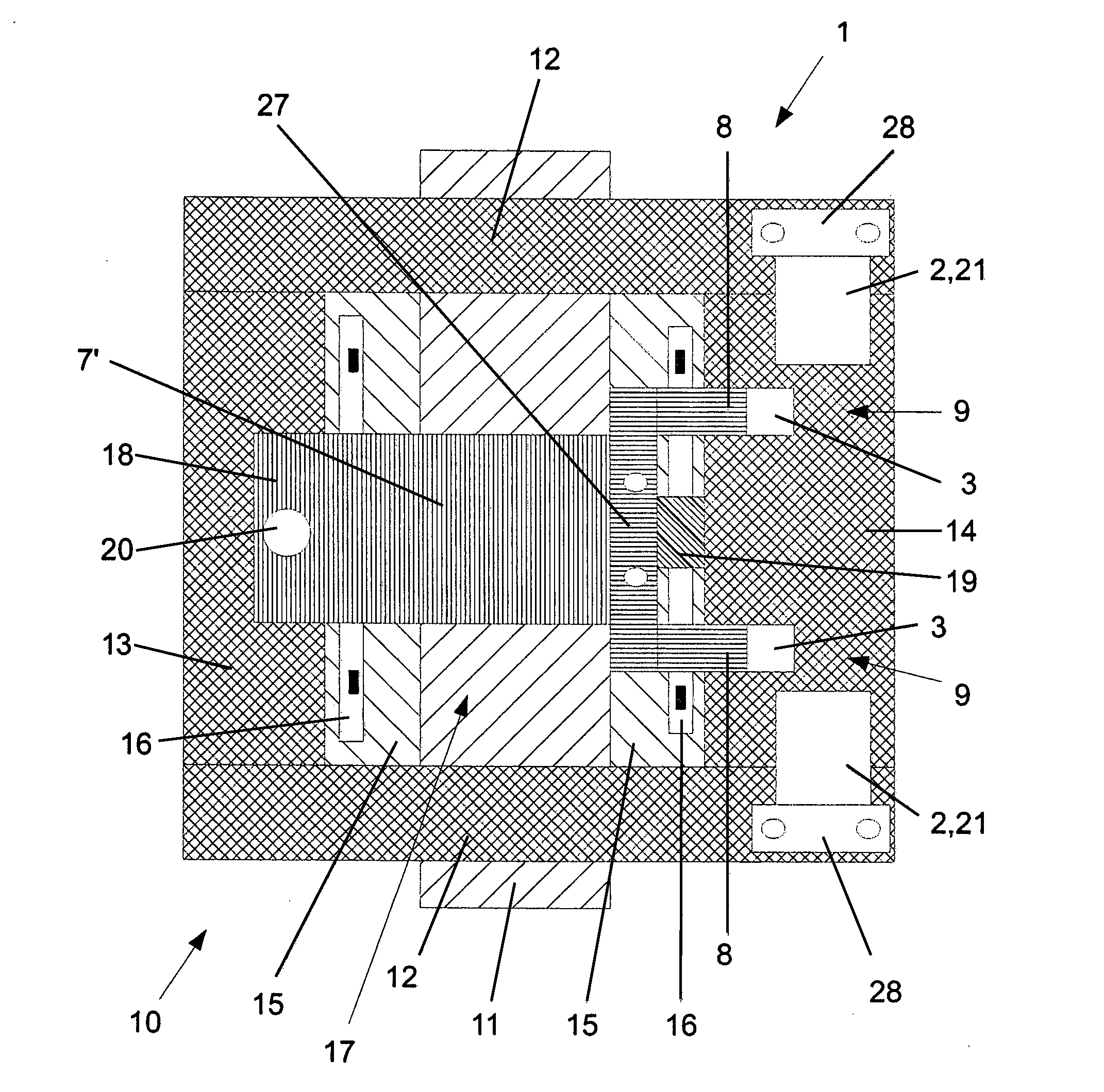
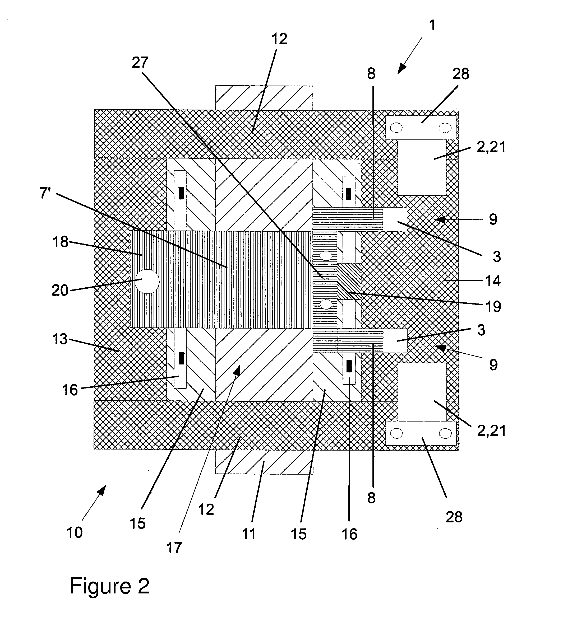
[0043]The measuring arrangement 1 includes a brake application force sensor 2, an evaluation unit 4 and a measurement object 7 with a target object 3. The measurement variable which is to be detected is a travel S which is carried out by the measurement object 7, here between the target object 3 or an element 23 which is assigned to the target object 3, as result of a displacement (double arrow) of the measurement object 7 relative to the parallel to a pickup device of the brake application force sensor 7 or at a right angle to a pickup longitudinal axis 22. The measurement object 7 is a component or a section of such a component which can move in the direction of the double arrow ...


PUM


Abstract

A measuring arrangement for brake application force measurement of a disc brake, includes two components of the disc brake which can be displaced relative to each other along a travel path when a brake application force is applied, at least one brake application force sensor with a housing; a measurement object which can be permanently connected to one or the other of the two components and having at least one element or at least one target object which has at least one such element for contact-free interaction with the brake application force measurement sensor; and an evaluation unit. The brake application force sensor is designed for the detection of a displacement of the measurement object along the path with the evaluation unit for the conversion of the detected displacement in a measurement variable as a measurement for the brake application force. The brake application force sensor and the measurement object can be mounted with each of the two components in a removable manner. The measuring arrangement is characterized in that the brake application force sensor is arranged outside the path of the measurement object and with the observation direction thereof arranged perpendicular to the path.

Description

CROSS REFERENCE TO RELATED APPLICATIONS[0001]This application is a continuation of PCT International Application No. PCT / EP2013 / 001085, filed Apr. 12, 2013, which claims priority under 35 U.S.C. §119 from German Patent Application No. 10 2012 007 471.9, filed Apr. 13, 2012, the entire disclosures of which are herein expressly incorporated by reference.BACKGROUND AND SUMMARY OF THE INVENTION[0002]The invention relates to a measuring arrangement for brake application force measurement of a disc brake. It also relates to a corresponding disc brake.[0003]Disc brakes can have different measuring arrangements for detecting a brake application force, wherein for this purpose, for example, pressure sensors are used in a hydraulic brake. However, a disc brake on a vehicle is subjected to relatively extreme operating conditions which can influence in different ways a measurement variable which correlates with the brake application force of the disc brake.[0004]A measuring arrangement for brak...

Claims


Application Information

Patent Timeline
IPC IPC(8): B60T17/22G01L5/28F16D66/00B60T1/06F16D55/22
CPCB60T17/22B60T1/065F16D2066/005F16D66/00G01L5/28F16D55/22F16D2066/003F16D2066/006
Inventor BAUMGARTNER, JOHANNWERTH, ALEXANDERSEIDENSCHWANG, MATTHIAS
Owner KNORR-BREMSE SYST FUER NUTZFAHRZEUGE GMBH
Why Eureka
Try Eureka