Door handle unit having a linear damper

a technology of linear damper and door handle, which is applied in the direction of door/window fittings, mechanical equipment, wing knobs, etc., can solve the problems limiting the reduction of the operating physical force, and the one-way rotary damper, etc., to achieve the effect of reducing the operating physical for

Inactive Publication Date: 2015-02-05
FUJI LATEX
View PDF5 Cites 12 Cited by
  • Summary
  • Abstract
  • Description
  • Claims
  • Application Information

AI Technical Summary

Benefits of technology

[0007]An object of the present invention is to provide a door handle unit capable of further reducing the operating physical force when manually rotating the door handle.
[0009]According to the aspect, when manually rotating the door handle by the rotational manipulation to operate the latch, the linear damper does not act on the door handle and not produce a resistance torque, thereby to reduce an operating physical force for the rotational manipulation.

Problems solved by technology

When manually rotating the door handle by the rotational manipulation in order to operate a latch, the rotary damper does not fulfill the function.
The one-way rotary damper, however, produces a resistance torque due to a seal or the like of the damper even when manually rotating the door handle from the original rotational position.
Therefore, there is a limit in reducing an operating physical force when manually rotating the door handle.

Method used


Image

  • Door handle unit having a linear damper
  • Door handle unit having a linear damper
  • Door handle unit having a linear damper

Examples


Embodiment Construction

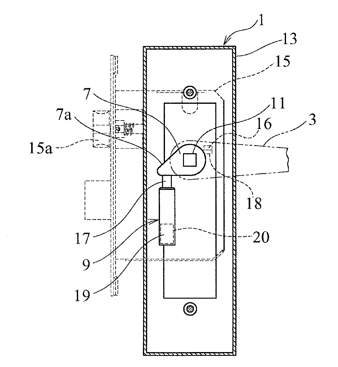
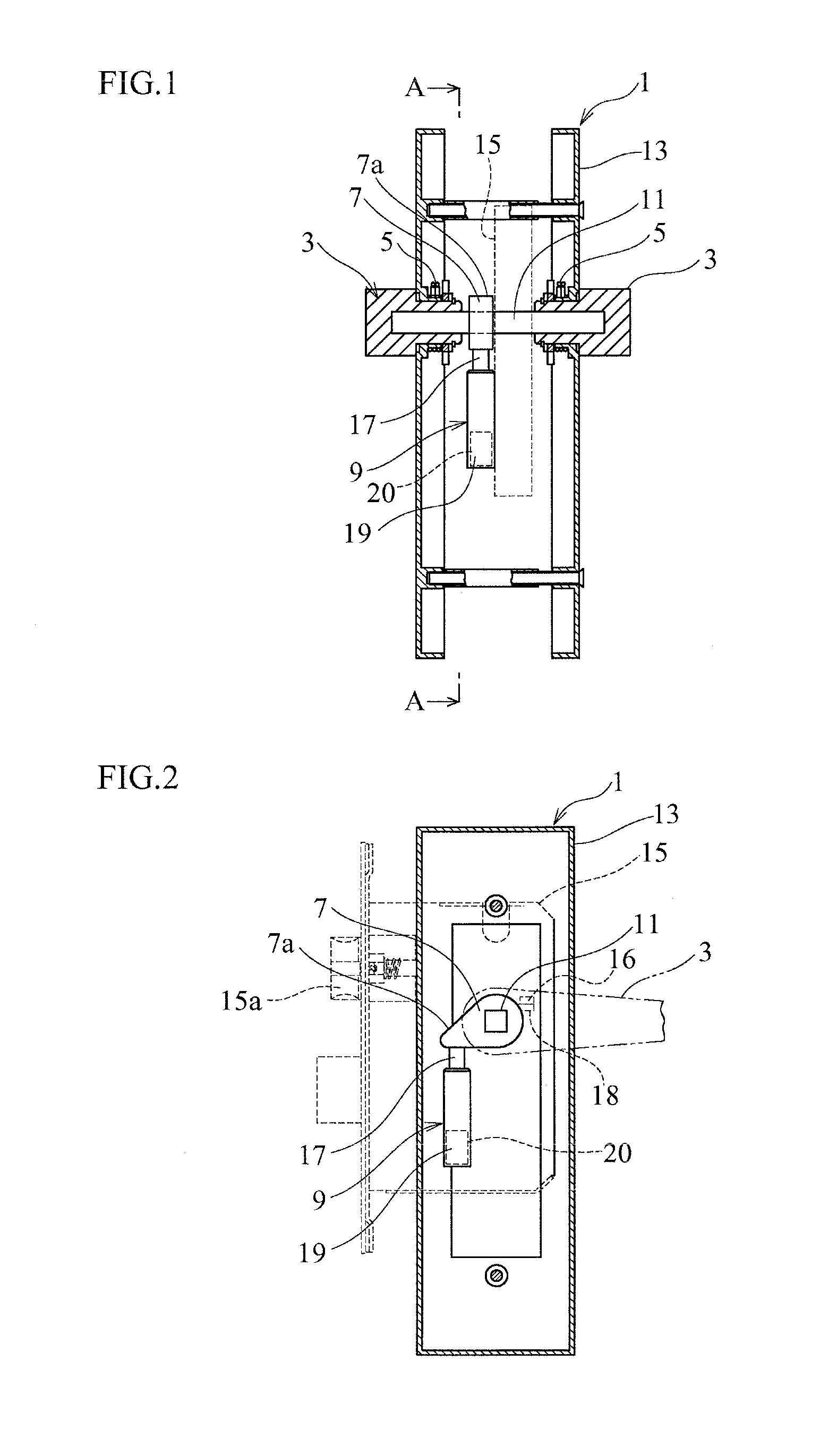
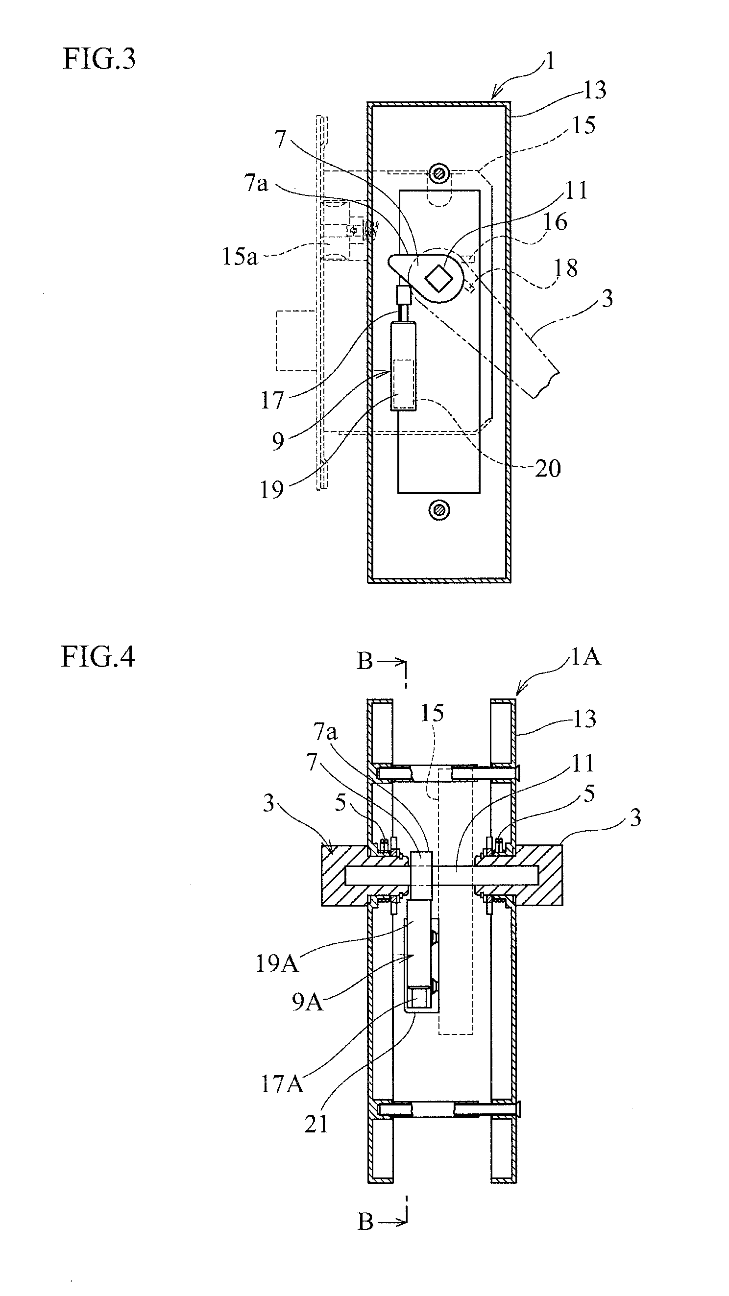
[0017]Embodiments according to the present invention will be explained. A door handle unit of each embodiment is capable of further reducing an operating physical force when manually rotating a door handle.

[0018]For this, the door handle unit includes a unit case, a door handle, a rotary shaft, a latch, a spring, an arm, and a linear damper. The door handle is rotatably supported with the unit case for rotational manipulation. The rotary shaft is connected to the door handle to rotate together with the door handle. The latch is connected to the rotary shaft so as to be operated by the rotary shaft rotating through the rotational manipulation of the door handle. The spring applies a biasing force to rotate the door handle back into an original rotational position before the rotational manipulation. The arm is provided on the rotary shaft. The linear damper contacts with the arm to damp a rotation of the door handle only when the door handle rotates back into the original rotational p...


PUM


Abstract

A door handle unit includes an unit case, a door handle rotatably supported with the unit case for rotational manipulation, a rotary shaft connected to the door handle so as to be rotated through the rotational manipulation of the door handle, a latch connected to the rotary shaft so as to be operated by the rotary shaft rotating through the rotational manipulation of the door handle, a spring applying a biasing force to return the door handle to an original rotational position before the rotational manipulation, an arm provided on the rotary shaft, and a linear damper contacting with the arm to damp the rotation of the door handle only when the door handle returns to the original rotational position before the rotational manipulation.

Description

BACKGROUND OF THE INVENTION[0001]1. Field of the Invention[0002]The present invention relates to a door handle unit for buildings, vehicles, or the like.[0003]2. Description of Related Art[0004]Conventionally, there is a door handle unit as disclosed in JP2002-235471A. The door handle unit includes a rotatably-supported door handle for rotational manipulation by a person, a coil spring for returning the door handle, and a one-way rotary damper for damping the returning door handle.[0005]When manually rotating the door handle by the rotational manipulation in order to operate a latch, the rotary damper does not fulfill the function. When releasing a hand from the door handle after the operation of the latch, the door handle rotates back into an original rotational position according to a biasing force of the coil spring so that a contact portion on the door handle comes into contact with a stopper on a stationary side of the door handle unit. As a result, the door handle is positione...

Claims


Application Information

Patent Timeline
Patent Type & Authority Applications(United States)
IPC IPC(8): E05B17/00E05B7/00
CPCE05B7/00E05B17/0041E05B1/0053E05B77/42Y10T292/57
Inventor YOKOO, TAKASHI
Owner FUJI LATEX
Why Eureka
Try Eureka