Spindle motor and disk drive apparatus

a technology of disk drive and spindle motor, which is applied in the direction of sliding contact bearings, recording information storage, instruments, etc., can solve the problems of reducing the rigidity of the base plate, the inability to minimize the height of the motor, and the inability to achieve a reduction in the axial thickness. , to achieve the effect of preventing an adhesive from overflowing and reducing the thickness of the base member

Active Publication Date: 2015-02-05
NIPPON DENSAN CORP
View PDF7 Cites 9 Cited by
  • Summary
  • Abstract
  • Description
  • Claims
  • Application Information

AI Technical Summary

Benefits of technology

The spindle motor in this invention prevents adhesive from leaking while reducing the base member's thickness.

Problems solved by technology

However, when the connection portion of the flexible circuit board is arranged directly under the motor as is the case with the above structure, it is impossible to minimize the height of the motor to achieve a reduction in the axial thickness thereof.
On the other hand, an attempt to reduce the thickness of the base plate for the accommodation of the connection portion of the flexible circuit board leads to a problem of a reduction in rigidity of the base plate.

Method used


Image

  • Spindle motor and disk drive apparatus
  • Spindle motor and disk drive apparatus
  • Spindle motor and disk drive apparatus

Examples


Embodiment Construction

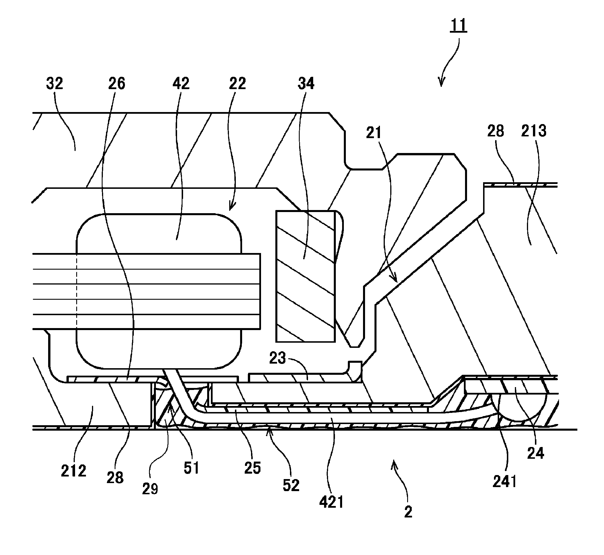
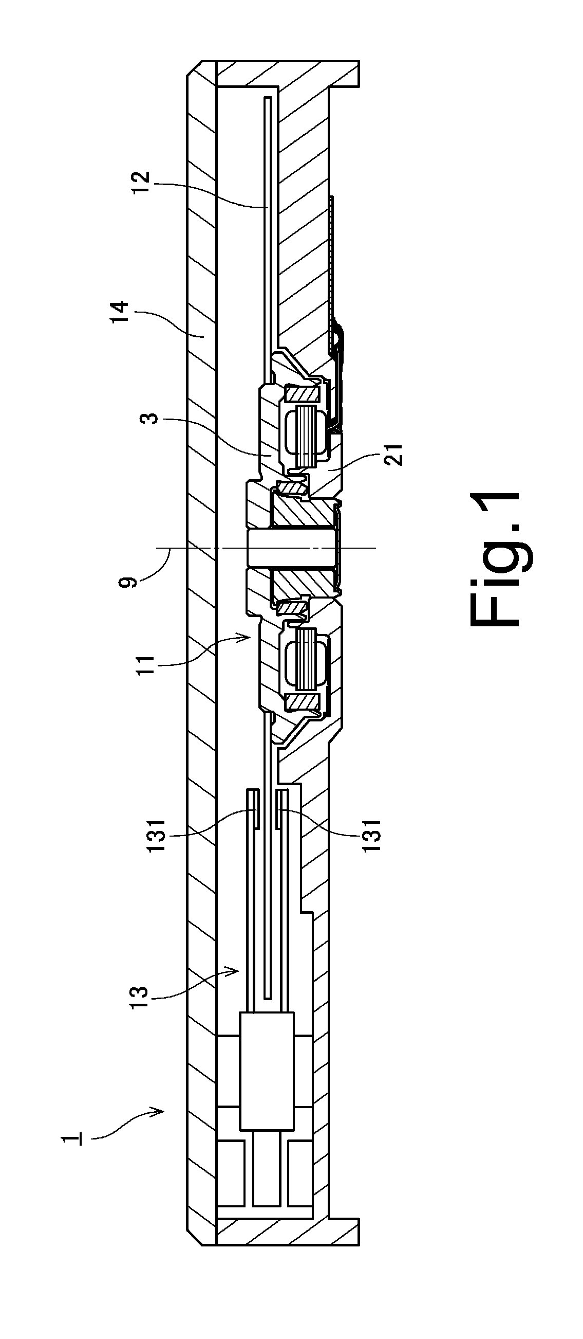
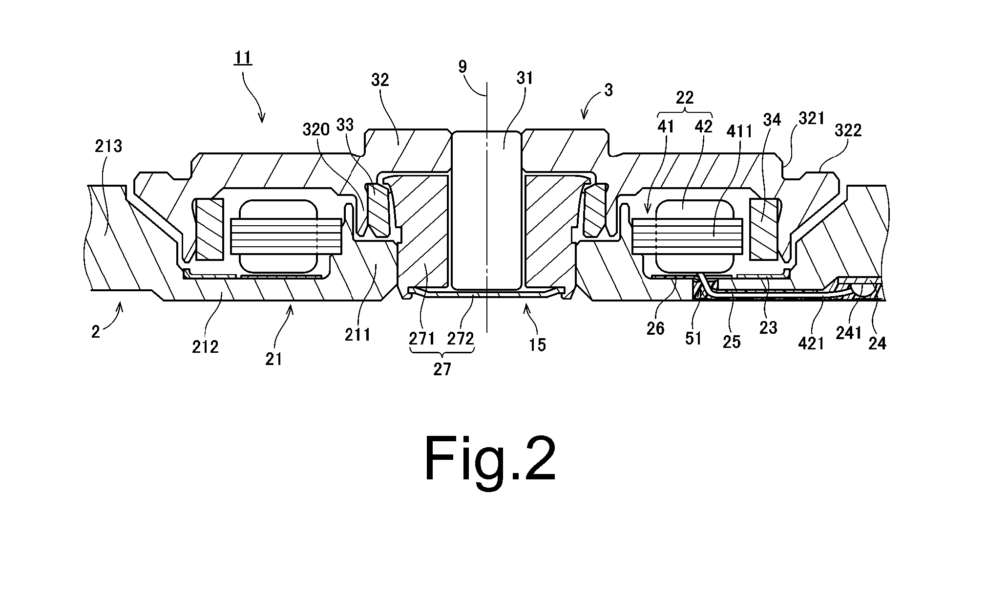
[0015]It is assumed herein that a direction parallel to or substantially parallel to a rotation axis of a spindle motor is referred to by the term “axial direction”, “axial”, or “axially”, that directions perpendicular to or substantially perpendicular to the rotation axis of the spindle motor are each referred to by the term “radial direction”, “radial”, or “radially”, and that a direction along or substantially along a circular arc centered on the rotation axis of the spindle motor is referred to by the term “circumferential direction”, “circumferential”, or “circumferentially”. It is also assumed that a position closer to the rotation axis of the spindle motor is referred to as an “inside”, and that a position farther away from the rotation axis of the spindle motor is referred to as an “outside”. It is also assumed herein that an axial direction is a vertical direction, and that a side on which a stator is arranged with respect to a base member is defined as an upper side. The s...


PUM


Abstract

A spindle motor includes a stationary portion and a rotating portion. The stationary portion includes a base member, a stator core, coils, and a circuit board. The base member includes a middle region, a peripheral region, jetty portions, a recessed portion, and at least one through hole. The jetty portions are positioned at least axially below the peripheral region, and include a pair of extension portions. The recessed portion is arranged inside the jetty portions, and a portion of the circuit board is arranged in the recessed portion. The at least one through hole is arranged to pass through the middle region in an axial direction. The recessed portion is covered with a sealant.

Description

BACKGROUND OF THE INVENTION[0001]1. Field of the Invention[0002]The present invention relates to a spindle motor and a disk drive apparatus.[0003]2. Description of the Related Art[0004]Spindle motors arranged to rotate disks are installed in hard disk drive apparatuses and optical disk drive apparatuses. Such a spindle motor includes a stationary portion fixed to a housing of the apparatus, and a rotating portion arranged to rotate while supporting the disk(s). While the spindle motor is running, a torque centered on a rotation axis is produced by magnetic flux generated between the stationary portion and the rotating portion, so that the rotating portion is caused to rotate with respect to the stationary portion.[0005]Here, JP-A 2009-189157 discloses the following structure: “a connection portion of a flexible circuit board connected with an armature is accommodated in a recessed portion defined in a middle region 213 of a lower surface of a base plate of a motor, and a led-out por...

Claims


Application Information

Patent Timeline
IPC IPC(8): H02K5/04H02K3/46H02K5/22G11B19/20
CPCH02K5/04H02K5/225H02K3/46G11B19/2009F16C2370/12G11B19/2036F16C17/107F16C33/745
Inventor SHIRAISHI, MASAHIROWATANABE, TSUCHITSUGU
Owner NIPPON DENSAN CORP
Why Eureka
Try Eureka