Crimping pliers

Active Publication Date: 2015-02-12
YEN CHAO CHIN
View PDF4 Cites 4 Cited by
  • Summary
  • Abstract
  • Description
  • Claims
  • Application Information

AI Technical Summary

Problems solved by technology

Nevertheless, the attachment of the conductive wire and the connector typically requires the use of crimping pliers for attaching the conductive wire and the connector firmly together by compression.
However, such known crimping pliers still have the following drawbacks.
Since guiding slots are provided inside the base for the crimping portion of the crimping member

Method used


Image

  • Crimping pliers
  • Crimping pliers
  • Crimping pliers

Examples


Embodiment Construction

[0016]The following provides a detailed description of the present invention along with the accompanied drawings; however, it shall be understood that the accompanied drawings are provided for illustrative purposes only, which shall not be treated as limitations of the present invention.

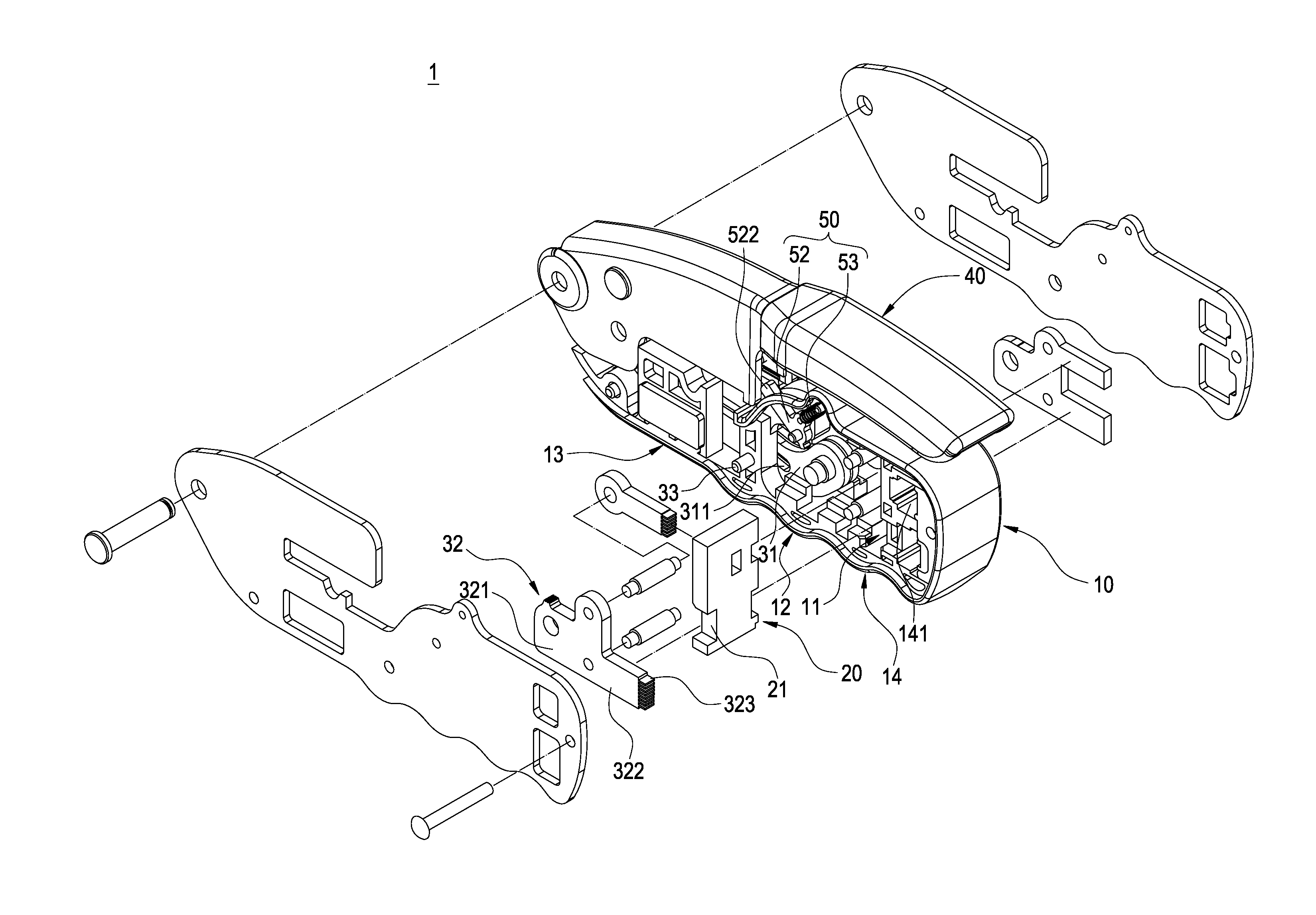
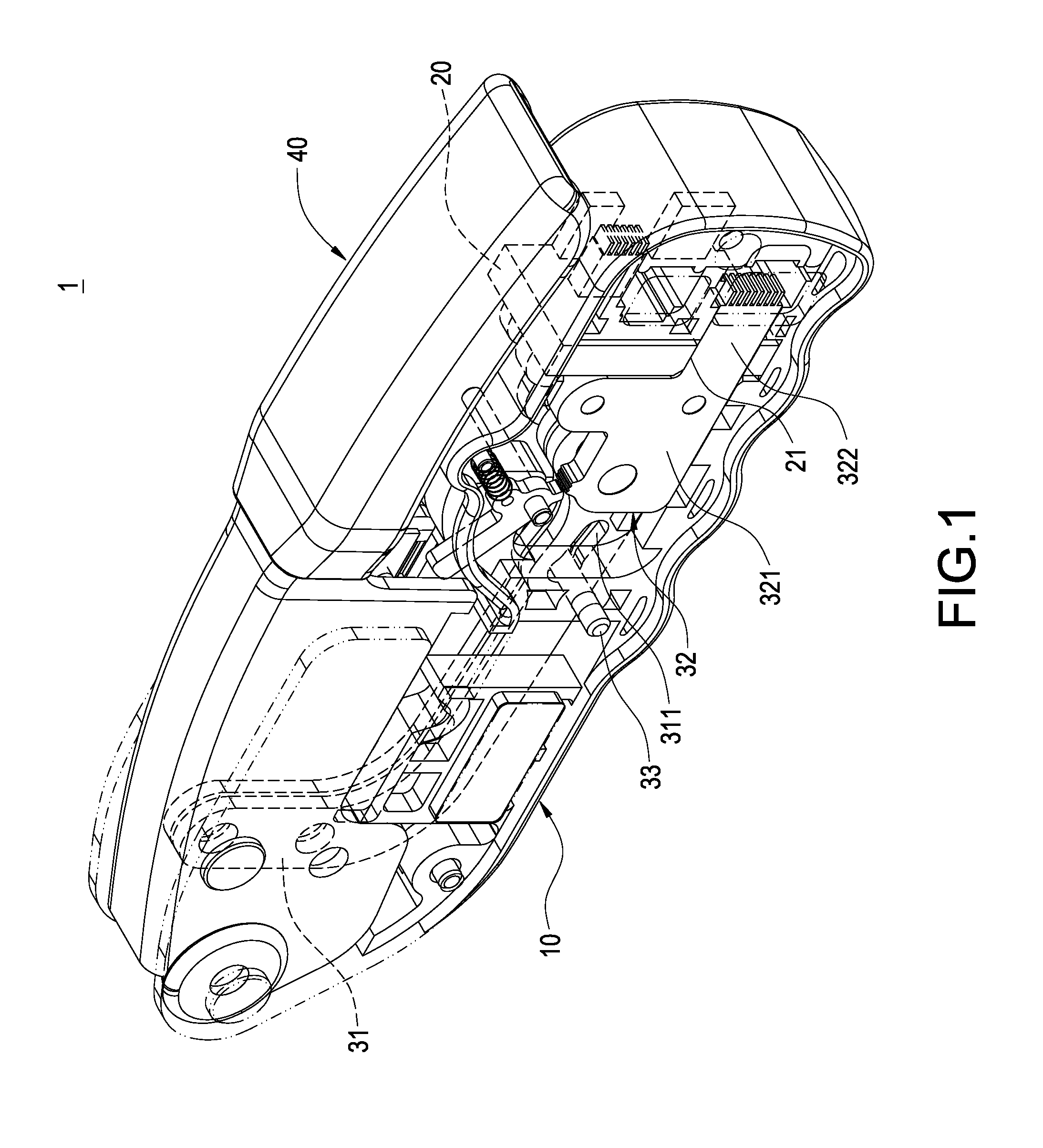
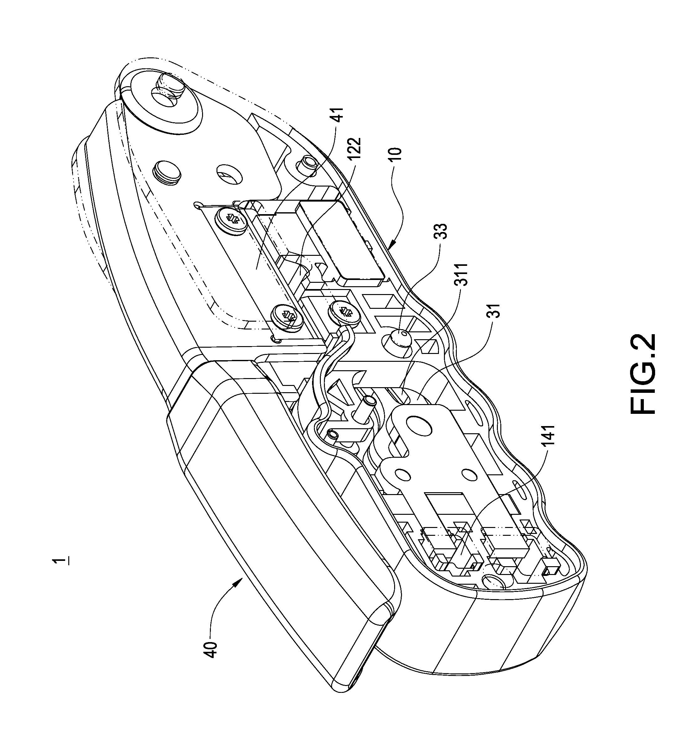
[0017]Please refer to FIG. 1 and FIG. 2, showing a perspective view and another perspective view of the present invention respectively. The present invention provides a crimping pliers 1 comprising a base 10, a guiding plate 20, a crimping member 30 and a compression handle 40.

[0018]Please refer to FIG. 3 and FIG. 4, showing an exploded view and a cross sectional view of the present invention respectively. The base 10 includes a receiving space 11, and the base 10 comprises a main body section 12, a pivotal attachment portion 13 and an actuation section 14. The pivotal attachment portion 13 and the actuation section 14 extend from two end portions of the main body section 12 respectively. The upper s...


PUM

PropertyMeasurementUnit
Forceaaaaaaaaaa
Abrasion resistanceaaaaaaaaaa
Elasticityaaaaaaaaaa

Abstract

A crimping pliers (1) includes a base (10), a guiding plate (20), a crimping member (30) and a compression handle (40). The base (10) includes a receiving space (11), a pivotal attachment portion (13) and an actuation section (14) having a crimping opening (141). The guiding plate (20) with a guiding hole (21) is installed in the receiving space (11) and corresponding to the crimping opening (141). The crimping member (30) is installed inside the receiving space (11) and comprises a connecting rod (31) attached to a sliding member (32) having a crimping portion (322) connected to the guiding hole (21) and corresponding to the crimping opening (141). The compression handle (40) is configured to drive the crimping portion (322) to move inside the crimping opening (141). Therefore, a uniform compression force is ensured to be applied to the connector and the conductive wire by the crimping portion.

Description

BACKGROUND OF THE INVENTION[0001]1. Field of the Invention[0002]The present invention is related to a hand tool, in particular, to a crimping pliers for attaching a conductive wire and a connector firmly together by compression.[0003]2. Description of Related Art[0004]Transmission of signals among electronic products, electronic devices or electronic instruments are typically achieved via the connection between one conductive wire and another conductive wire; whereas the connection between the conductive wire and another conductive wire typically requires the attachment of the conductive wires onto a connector, followed by connecting the connector with another connector in order to allow the electronic connection to be established between the conductive wire and another conductive wire. Nevertheless, the attachment of the conductive wire and the connector typically requires the use of crimping pliers for attaching the conductive wire and the connector firmly together by compression....

Claims


Application Information

Patent Timeline
IPC IPC(8): H01R43/042
CPCH01R43/042B25B27/146B25F1/00
Inventor YEN, CHAO-CHIN
Owner YEN CHAO CHIN
Why Eureka
Try Eureka