Member for slot die coater, movable member for slot die coater, and slot die coater including the members to produce electrode

Active Publication Date: 2015-02-26
LG ENERGY SOLUTION LTD
View PDF3 Cites 3 Cited by
  • Summary
  • Abstract
  • Description
  • Claims
  • Application Information

AI Technical Summary

Benefits of technology

The present invention relates to a member for a slot die coater and a slot die coater for producing an electrode. The member or the slot die coater includes a slope surface for guiding the flow of electrode slurry, which prevents the slurry from stagnating in the slot die coater. This reduces coating defects and maintains uniform distribution of the flow rates of the slurry at the outlet of the slot die coater. The invention also includes a movable member that selectively forms the slope surface and adjusts the ratio of the stagnation region, providing more flexibility in the production process.

Problems solved by technology

When the agglomerate is fitted in a flow passage in the slot die coater or is discharged out of the slot die coater, a coating layer may have an uneven thickness, or a coating defect such as a streak may occur.

Method used


Image

  • Member for slot die coater, movable member for slot die coater, and slot die coater including the members to produce electrode
  • Member for slot die coater, movable member for slot die coater, and slot die coater including the members to produce electrode
  • Member for slot die coater, movable member for slot die coater, and slot die coater including the members to produce electrode

Examples


embodiment 1

[0067]FIG. 3 is an exploded perspective view illustrating a slot die coater for producing an electrode according to a first embodiment of the present invention. FIG. 4 is a perspective view illustrating a state in which the slot die coater illustrated in FIG. 3 is assembled. For convenience, a shim illustrated in FIG. 3 is omitted from FIG. 4. FIG. 5 is a perspective view illustrating only an inner shape of the slot die coater after a member for the slot die coater is installed on the slot die coater illustrated in FIG. 4. FIG. 6 is a plan view illustrating the inner shape of the slot die coater illustrated in FIG. 5. FIG. 7 is a rear view illustrating the inner shape of the slot die coater illustrated in FIG. 5. FIG. 8 is a side view illustrating the inner shape of the slot die coater illustrated in FIG. 5. Referring to FIGS. 3 to 8, a slot die coater for producing an electrode will now be described in detail according to the first embodiment.

[0068]Referring to FIGS. 3 to 5, the sl...

embodiment 2

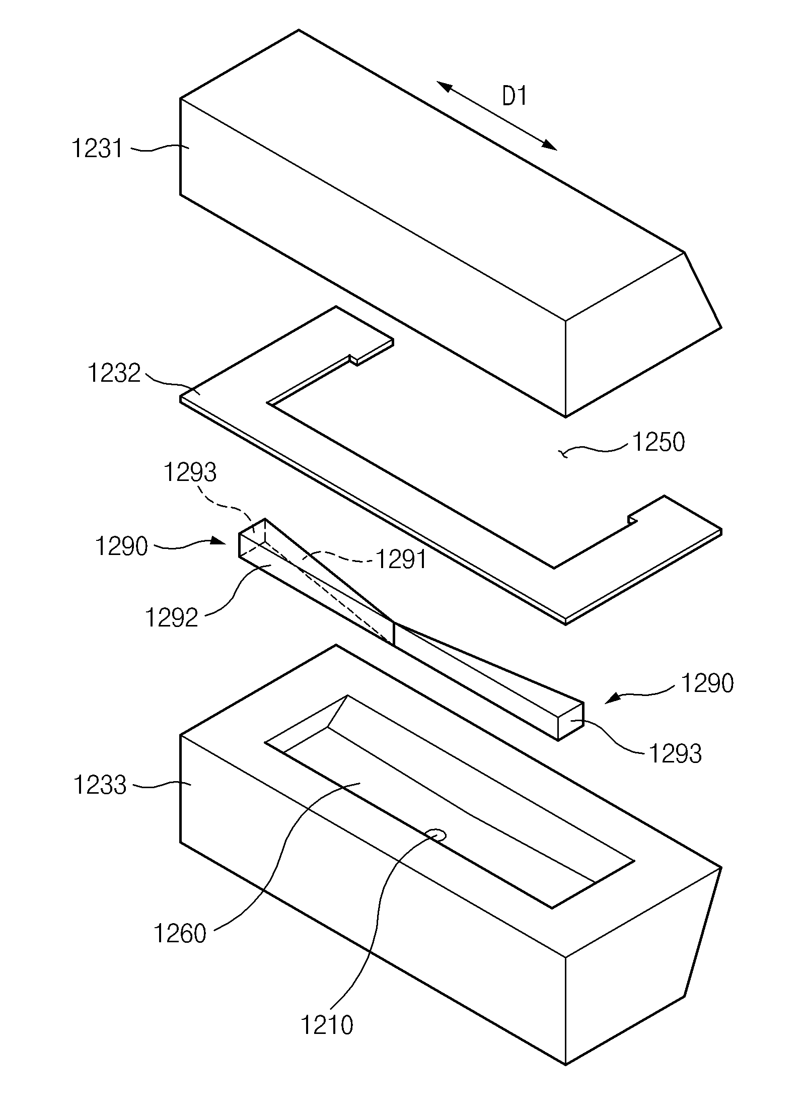
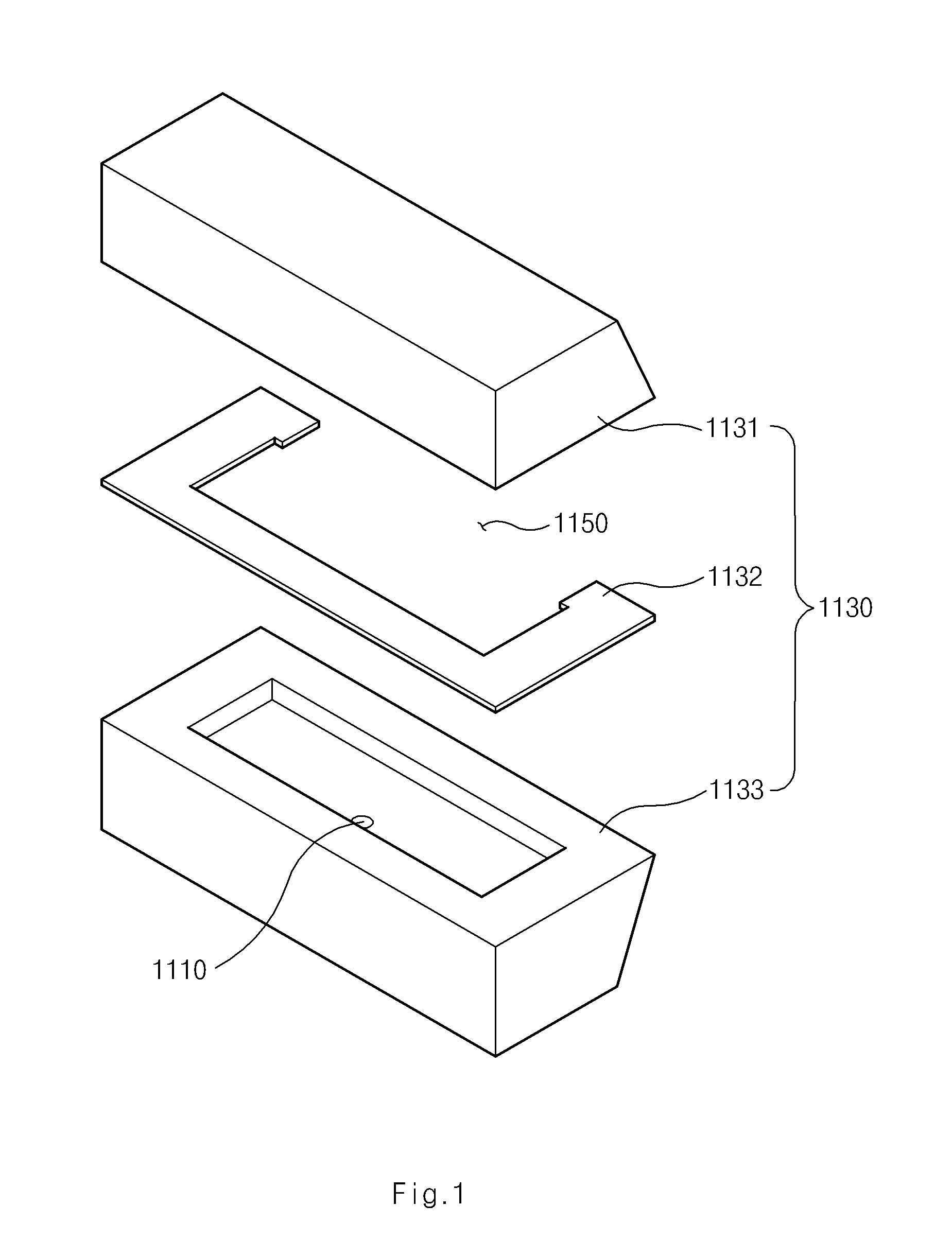
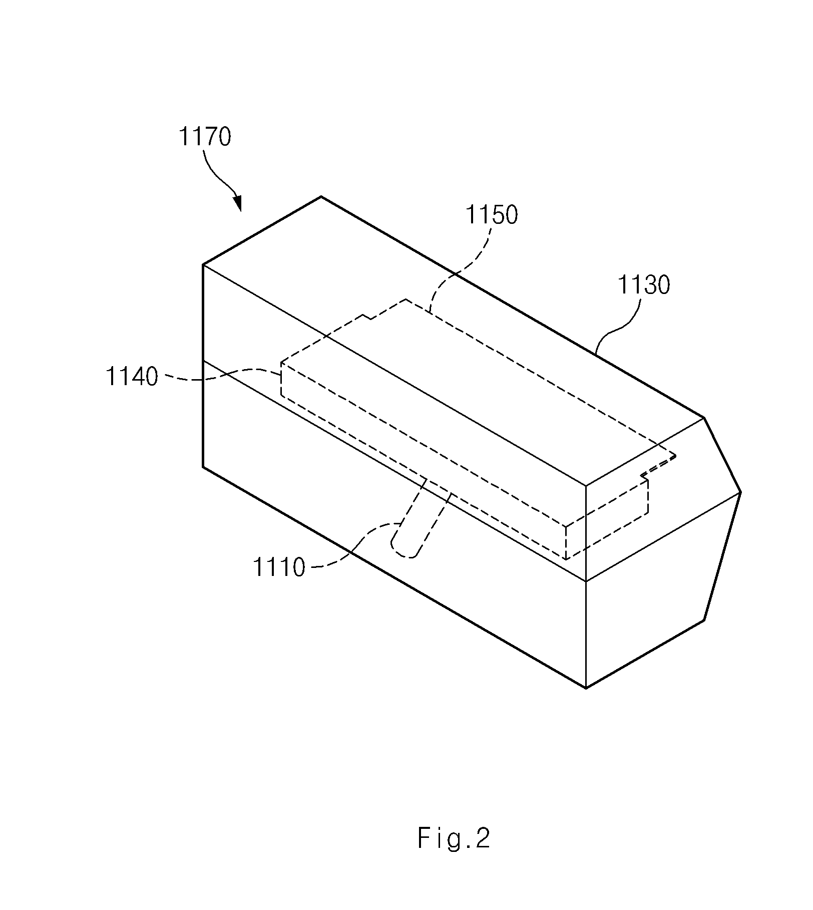
[0105]FIG. 26 is an exploded perspective view illustrating a slot die coater for producing an electrode according to a second embodiment of the present invention. FIG. 27 is a perspective view illustrating a state in which the slot die coater illustrated in FIG. 26 is assembled. For convenience, a shim illustrated in FIG. 26 is omitted from FIG. 27. A slot die coater for producing an electrode according to the current embodiment has a configuration similar to that of a slot die coater for producing an electrode according to the first embodiment. However, the second embodiment is different from the first embodiment in that a plate structure is provided as a member 1490 for a slot die coater. Parts, which are the same as (or correspond to) the previously-described parts, are denoted by the same (or corresponding) reference numerals, and a detailed description thereof will be omitted.

[0106]Referring to FIGS. 26 and 27, a slot die coater for producing an electrode according to the secon...

embodiment 3

[0107]FIG. 28 is an exploded perspective view illustrating a slot die coater for producing an electrode according to a third embodiment of the present invention. FIG. 29 is a perspective view illustrating only a movable member for the slot die coater illustrated in FIG. 28, which is installed in the slot die coater. FIG. 30 is a perspective view illustrating a state in which the slot die coater illustrated in FIG. 28 is assembled. For convenience, a shim illustrated in FIG. 28 is omitted from FIG. 30. FIG. 31 is a plan view illustrating the slot die coater of FIG. 30. FIG. 32 is a side view illustrating the slot die coater of FIG. 30. FIG. 33 is a bottom view illustrating the slot die coater of FIG. 30.

[0108]Referring to FIGS. 28 to 33, a slot die coater for producing an electrode will now be described according to the third embodiment.

[0109]The slot die coater according to the third embodiment includes: a supply hole 3210 for supplying electrode slurry to the slot die coater; a bod...


PUM


Abstract

Provided is a slot die coater that applies electrode slurry to metal foil to produce an electrode, the slot die coater including a die part, which includes a body having an inner space receiving the electrode slurry, a supply hole disposed in the body to supply the electrode slurry to the inner space, and a discharge hole disposed in the body to discharge the electrode slurry from the inner space to the metal foil, and a member for the slot die coater, which is removably installed in the inner space to form a slope surface in the inner space, or a movable member for the slot die coater, which selectively forms the slope surface.

Description

CROSS-REFERENCE TO RELATED APPLICATIONS[0001]This application claims the priority of Korean Patent Application No. 10-2013-0083475 filed on Jul. 16, 2013, Application No. 10-2013-0110127 filed on Sep. 13, 2013, Application No. 10-2014-0089034 filed on Jul. 15, 2014, and Application No. 10-2014-0089035 filed on Jul. 15, 2014 in the Korean Intellectual Property Office, the disclosures of which are incorporated herein by reference.FIELD OF THE INVENTION[0002]The present invention relates to a member for a slot die coater, a movable member for a slot die coater, and a slot die coater including the members to produce an electrode, and more particularly, to a member for a slot die coater, a movable member for a slot die coater, and a slot die coater including the members to produce an electrode, which decrease a volumetric ratio of a stagnation region in the slot die coater.DISCUSSION OF RELATED ART[0003]Secondary batteries are rechargeable, unlike primary batteries, and can be miniaturiz...

Claims


Application Information

Patent Timeline
IPC IPC(8): B05C5/02H01M4/139H01M4/04
CPCB05C5/0258B05C5/0254H01M2220/20H01M4/139H01M2220/30H01M4/0402H01M4/0409Y02E60/10
Inventor PARK, SUNG HYUNLEE, CHAE GYUIM, YE HOON
Owner LG ENERGY SOLUTION LTD
Why Eureka
Try Eureka