
Pipe coating repair system

a technology of coating repair system and pipe, which is applied in the direction of coatings, pipe elements, mechanical equipment, etc., can solve the problems of affecting the quality of pipe coating,

Inactive Publication Date: 2015-02-26
PRAGMATIC PIPELINE SOLUTIONS INC
View PDF10 Cites 5 Cited by
  • Summary
  • Abstract
  • Description
  • Claims
  • Application Information

AI Technical Summary

Benefits of technology

The invention provides a system for repairing a damaged portion of a fusion bonded epoxy coating on a steel body of a pipe. The system includes an epoxy patch for replacing the damaged portion and a housing with an opening for directing heated air into the cavity to cure the epoxy patch. An insulation strip is provided to prevent heat transfer to the undamaged portion of the coating. The method involves placing the epoxy patch on the exposed area of the steel body, positioning the housing over the pipe, and using the heat source to generate heated air which is mixed with air in the cavity to achieve a consistent temperature throughout for curing the epoxy patch.

Problems solved by technology

As is well known in the art, during pipeline construction, the epoxy coating typically is damaged or worn away in relatively small areas, for a variety of reasons.
In practice, preheating, and also heating the newly-applied epoxy to cure it, so that the epoxy bonds to the exposed steel to form the FBE coating, is a time-consuming and difficult task.
The task may be difficult for a variety of reasons.
For example, in very cold weather, preheating may take some time.
In addition, if fluid is flowing through the pipe on which the epoxy is to be cured, the fluid may affect the temperature of the pipe, sometimes in ways that are difficult to anticipate.
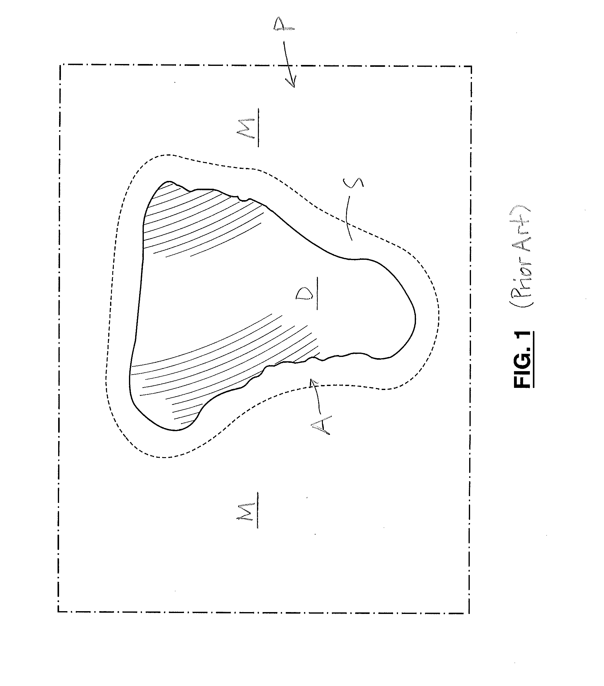
However, the area of pre-existing (securely bonded) epoxy material “M” surrounding the exposed steel in the area “A” is to be disturbed as little as possible.
However, in practice the epoxy often is provided with more heat than is appropriate using this method, with the result that the epoxy patch is not properly cured, and does not bond to the steel as required.
This is also difficult to control in practice, and may, if not properly controlled, cause the surrounding securely bonded coating “M” to burn.
In addition, use of the propane blowtorch may result in contamination of the exposed area “A”, which is then required to be sandblasted to remove the contamination.
However, in practice, the can tends to overheat, and its rim engaging the pre-existing material “M” conducts heat to such material, thereby causing the material “M” to melt.
Also, because the can is cylindrical and it is radially positioned relative to the pipe, the can's rim only partially engages the curved pipe, and heat escapes via the gaps between the pipe and the can, and is therefore wasted.

Method used


Image

  • Pipe coating repair system
  • Pipe coating repair system
  • Pipe coating repair system

Examples


Embodiment Construction

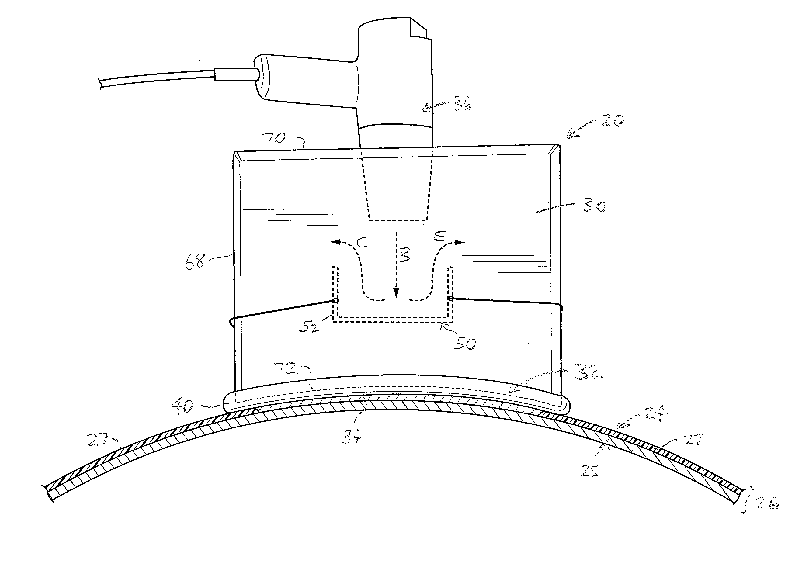
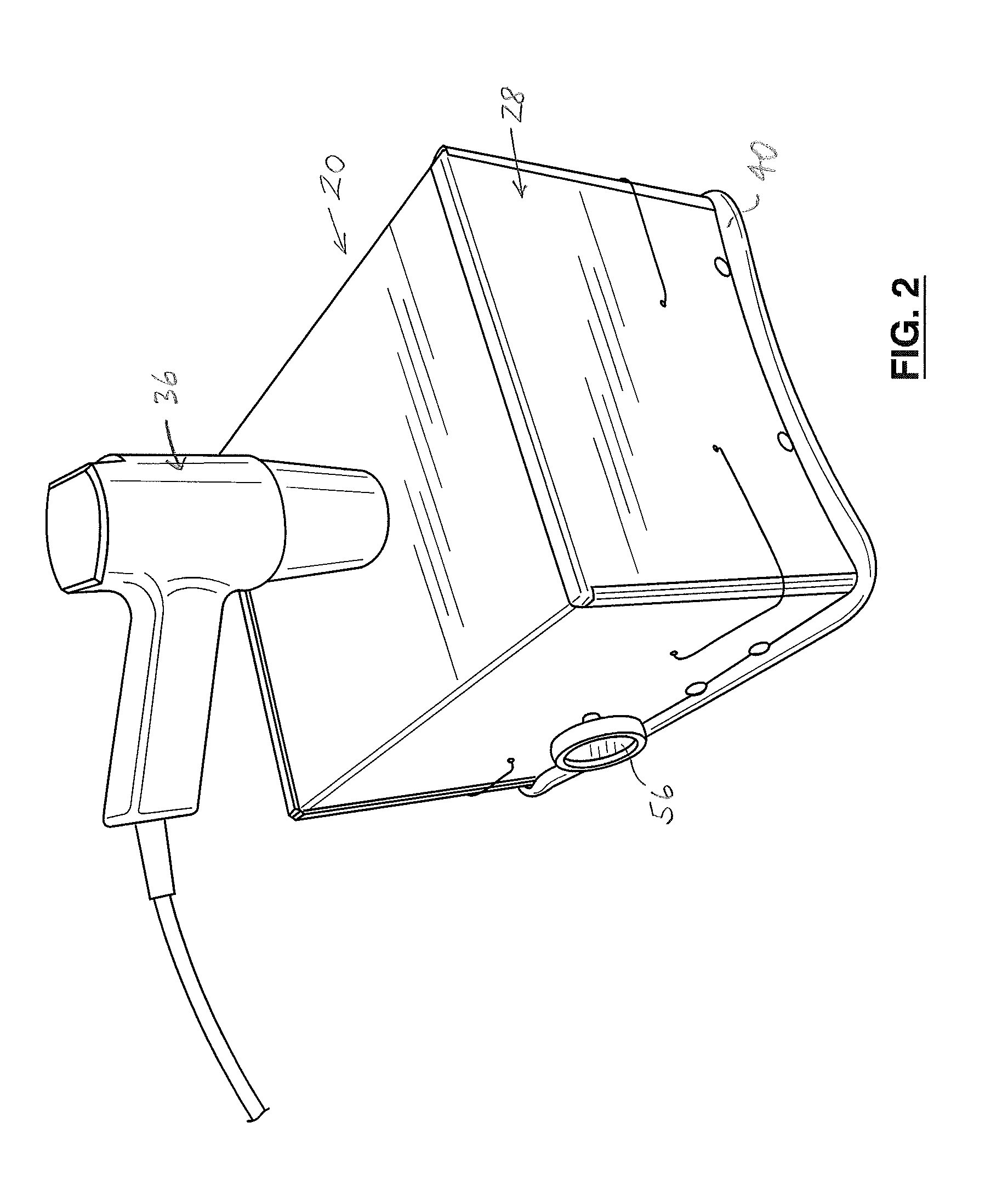
[0035]In the attached drawings, like reference numerals designate corresponding elements throughout. Reference is first made to FIGS. 2-7, 9, and 10 to describe an embodiment of an assembly of the invention indicated generally by the numeral 20. As will be described, the assembly 20 is for repairing a damaged portion 22 of a fusion bonded epoxy coating 24 on a steel body 25 of a pipe 26 (FIG. 5B) that is at least partially surrounded by an undamaged portion 27 of the coating 24 (FIG. 5C). In one embodiment, the assembly 20 preferably includes a housing 28 defining a cavity 30 therein and including one or more openings 32 in communication with the cavity 30 (FIGS. 2-4, 5B). Preferably, the housing 28 is attachable to the pipe 26 to locate the cavity 30 in communication with an epoxy patch 34 positioned on the steel body 25 to replace at least the damaged portion 22 (FIG. 5B). It is also preferred that the assembly 20 includes one or more heat sources 36 positioned for directing heate...


PUM

PropertyMeasurementUnit
surface temperatureaaaaaaaaaa
temperatureaaaaaaaaaa
dew pointaaaaaaaaaa

Abstract

An assembly for repairing a damaged portion of a fusion bonded epoxy coating on a steel body of a pipe at least partially surrounded by an undamaged portion of the coating. The assembly includes a housing defining a cavity therein and having an opening in communication with the cavity, the housing being attachable to the pipe to locate the cavity in communication with an epoxy patch positioned on the steel body to replace at least the damaged portion. The assembly also includes a heat source positioned for directing heated air heated thereby into the cavity, for curing the epoxy patch. The opening is at least partially defined by a perimeter, and the assembly includes an insulation strip positioned on the perimeter for impeding heat transfer from the housing to the undamaged portion of the coating when the housing is attached to the pipe.

Description

FIELD OF THE INVENTION[0001]The invention is a system for repairing a damaged portion of a fusion bonded epoxy coating on a pipe.BACKGROUND OF THE INVENTION[0002]Typically, a pipe “P” formed to be included in a pipeline includes a steel body “S” covered on its exterior with a fusion bonded epoxy coating (“FBE coating”) to protect the steel body (FIG. 1). (As will be described, embodiments of the invention are illustrated in the balance of the attached drawings.) The FBE coating is an epoxy-based coating that is also used to protect steel in other applications.[0003]Typically, the steel body's exterior surface is completely coated with the FBE coating when the pipe “P” is delivered to the site at which the pipe is to be installed. As is well known in the art, during pipeline construction, the epoxy coating typically is damaged or worn away in relatively small areas, for a variety of reasons. For example, a damaged portion “D” is illustrated in FIG. 1. For the purposes hereof, it will...

Claims


Application Information

Patent Timeline
Patent Type & Authority Applications(United States)
IPC IPC(8): F16L55/168F16L55/18
CPCF16L55/18F16L55/1683F16L58/1054
Inventor VOISIN, ANDREW
Owner PRAGMATIC PIPELINE SOLUTIONS INC
Learn More