Fusion Bonded Epoxy Removal Tool
- Summary
- Abstract
- Description
- Claims
- Application Information
AI Technical Summary
Problems solved by technology
Method used
Image

Examples
Embodiment Construction
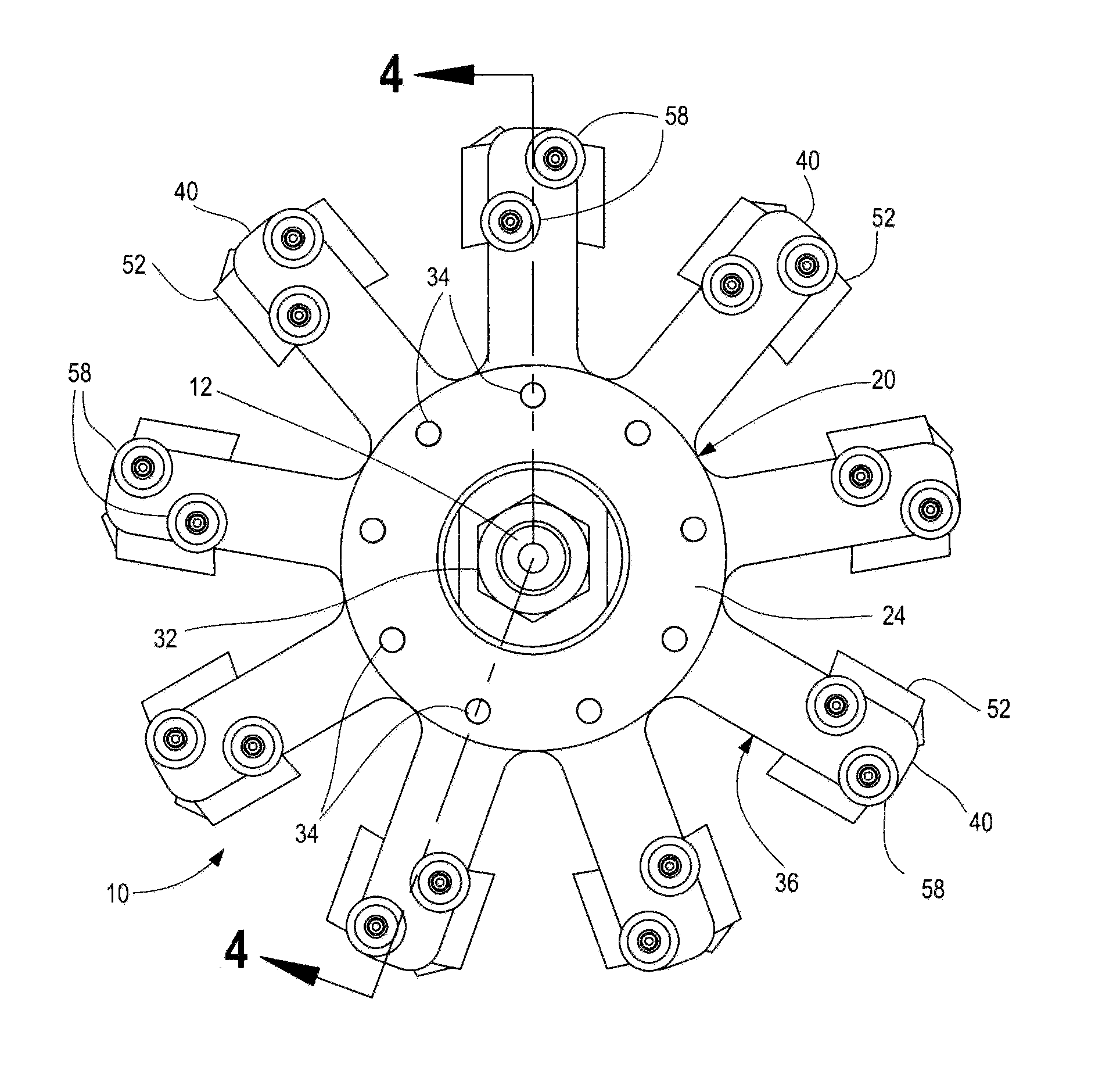
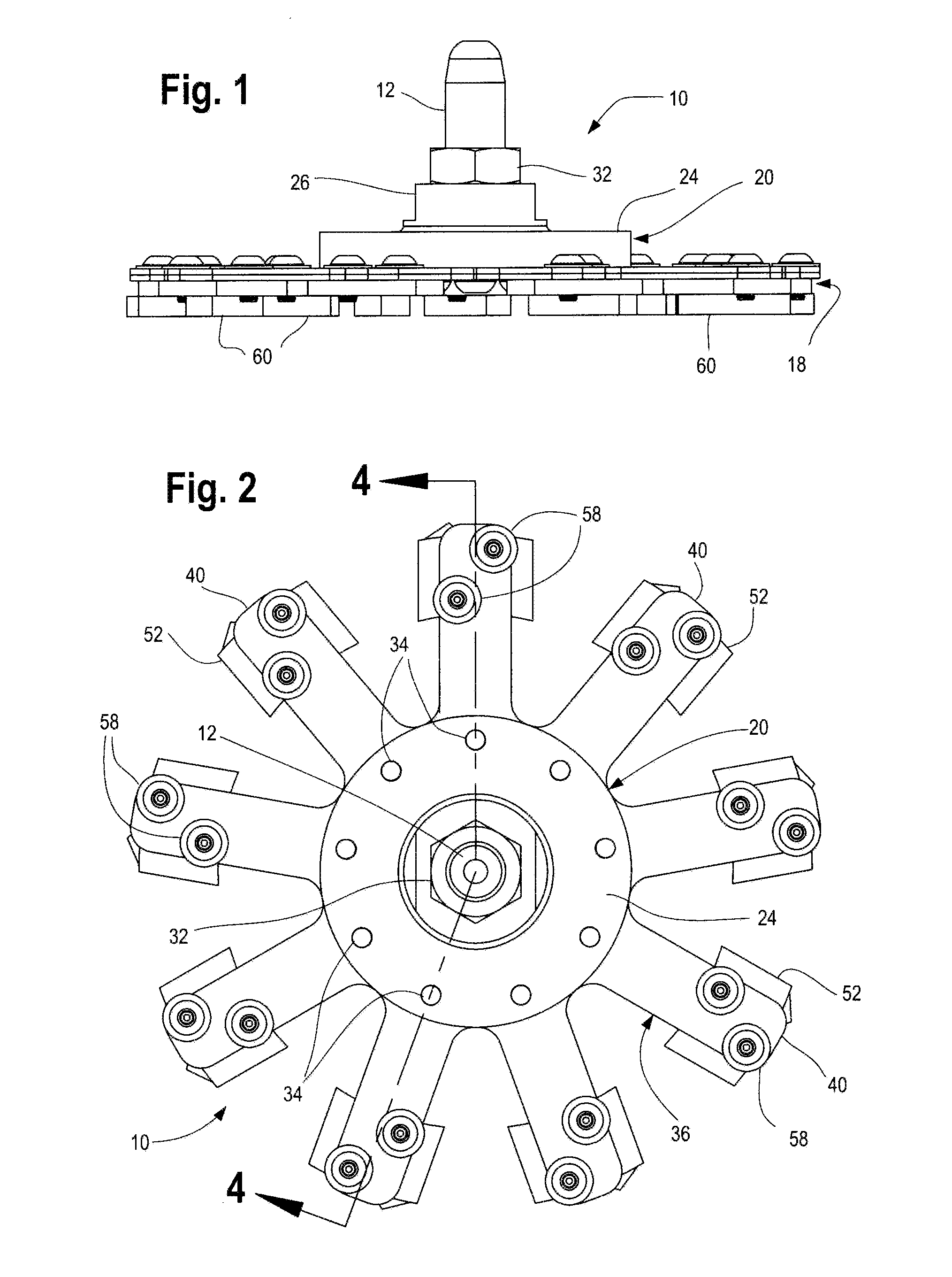
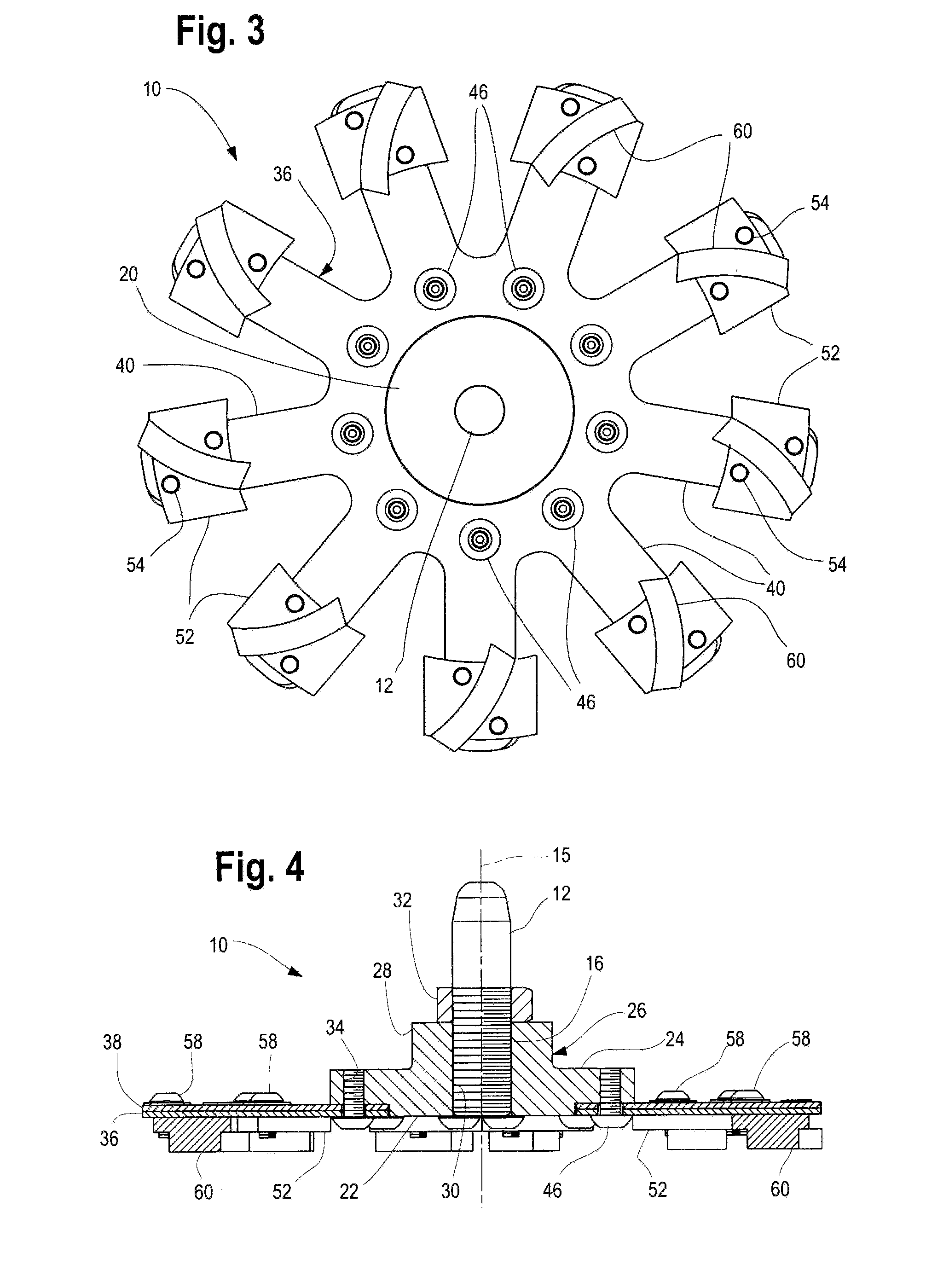
[0014]Referring to FIGS. 1 through 5, a tool in accordance with the present invention, a tool 10 is rotatably symmetric about an elongate shaft 12 having a rearward end 14 adapted for insertion into the retainer of a rotatable machine, not shown, a longitudinal axis 15, and a threaded outer end 16 for threadedly retaining a working end 18. For the purposes of this discussion the working end 18 of the tool 10 shall be considered the forward end of the tool 10, and elements described herein that are directed axially toward the working end 18 shall be considered the forward end thereof and elements that are directed axially toward end 14 of shaft 12 shall be considered the rearward end thereof.
[0015]The working end 18 is generally disc shaped in appearance and includes a centrally located hub 20 having a planar forward surface 22 and a parallel planar rearward surface 24. Extending rearwardly of the rearward surface 24 is a cylindrical projection 26 having opposing flats 28, 29. Extend...
PUM
 Abstract
Description
Claims
Application Information