Electromagnetic relay

a technology of electromagnetic relays and components, applied in electromagnetic relays, electrical apparatus, electromagnet relay details, etc., can solve the problems of increasing manufacturing costs and increasing so as to avoid an increase in the number of components, avoid an increase in the cost, and optimize the operation characteristics

Inactive Publication Date: 2015-02-26
FUJITSU COMPONENENT LTD
View PDF22 Cites 8 Cited by
  • Summary
  • Abstract
  • Description
  • Claims
  • Application Information

AI Technical Summary

Benefits of technology

[0009]According to an aspect of the present invention, operating characteristics may be optimized while preventing an increase in the number of components of the fixed core and avoiding a cost increase.

Problems solved by technology

Thus, the cylindrical fixed core part constitutes one part of the fixed core, and as a result, the number of components is increased and manufacturing costs are increased.

Method used


Image

  • Electromagnetic relay
  • Electromagnetic relay
  • Electromagnetic relay

Examples


Embodiment Construction

[0023]In the following, embodiments of the present invention will be described with reference to the accompanying drawings.

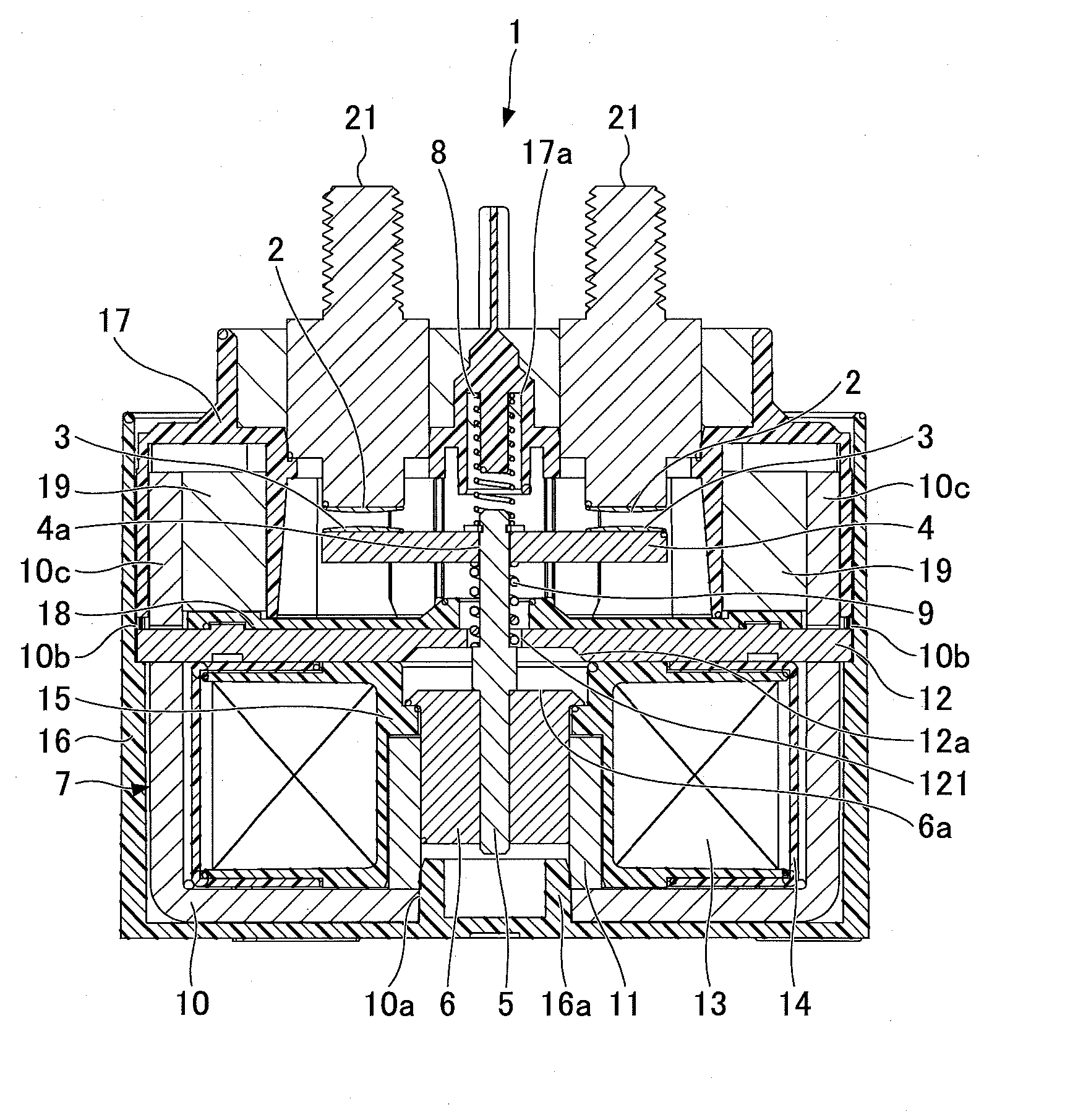
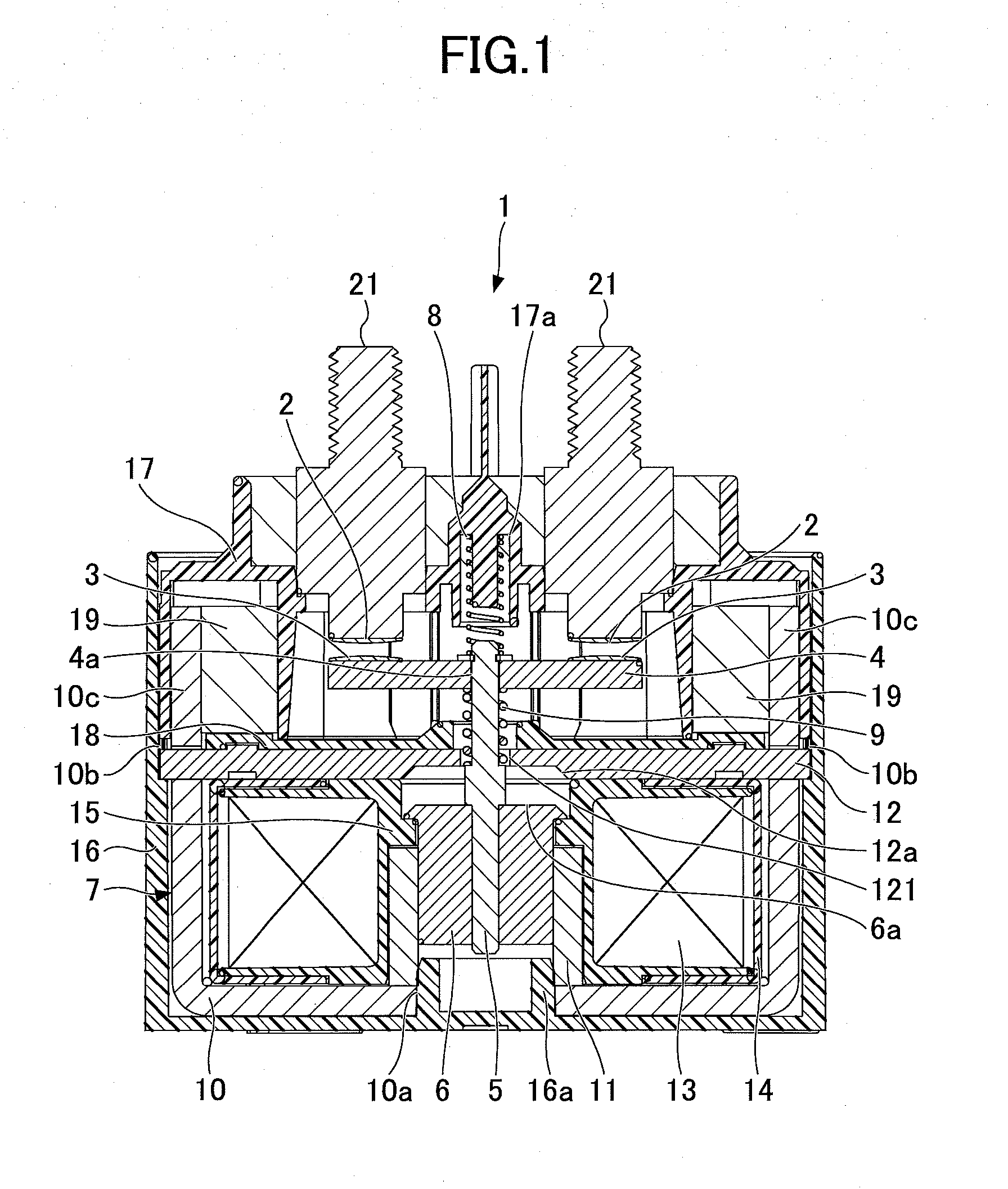
[0024]As illustrated in FIG. 1, an electromagnetic relay 1 according to an embodiment of the present invention includes a contact part including a pair of fixed contacts 2 and a pair of movable contacts 3 each corresponding to one of the fixed contacts 2. The movable contacts 3 are displaceable in directions toward and away from the fixed contacts 2. The electromagnetic relay 1 also includes a movable element 4 that holds the pair of movable contacts 3. The movable element 4 is configured to be movable in the directions toward and away from the fixed contacts 2. The electromagnetic relay 1 further includes a shaft 5 (axial core) and a plunger 6 (movable core). The shaft 5 is connected to the movable element 4. The plunger 6 is connected to the shaft 5 and is displaceable. Note that in the following descriptions, with respect to the displacement directions of the...


PUM


Abstract

An electromagnetic relay includes a contact part including a fixed contact and a movable contact, and a drive part including a fixed core and a movable core. The movable core is connected to the movable contact via an axial core. The fixed core includes a plate member, which is positioned between the contact part and the drive part and includes a through hole through which the axial core is inserted. The movable core includes a convex part protruding in a direction opposing the plate member. The plate member includes a concave part opposing the convex part and having a shape corresponding to the convex part.

Description

BACKGROUND OF THE INVENTION[0001]1. Field of the Invention[0002]The present invention relates to an electromagnetic relay.[0003]2. Description of the Related Art[0004]In electromagnetic relays, passage and blockage of a current in an electric circuit is realized by opening / closing a contact part including a fixed contact and a movable contact. A drive unit for moving the movable contact of the contact part toward and away from the fixed contact includes a fixed core and a movable core. The fixed core includes a cylindrical fixed core part that is arranged opposite the movable core. In order to adjust the attraction force and optimize operating characteristics, the side of the movable core opposing the cylindrical fixed core part is arranged into a conical shape, and the side of the cylindrical fixed core part opposing the movable core is arranged to have a stepped hole corresponding to the conical shape of the movable core (See e.g. Japanese Patent No. 4840533).[0005]In the electrom...

Claims


Application Information

Patent Timeline
Patent Type & Authority Applications(United States)
IPC IPC(8): H01H50/60H01H50/36H01H50/18
CPCH01H50/60H01H50/36H01H50/18H01H50/20H01H50/546H01H2050/365H01H50/00H01H50/16H01H50/38
Inventor KUBONO, KAZUOHASEGAWA, YOICHI
Owner FUJITSU COMPONENENT LTD
Why Eureka
Try Eureka