Heat dissipation device

Active Publication Date: 2015-02-26
ASIA VITAL COMPONENTS SHENZHEN CO LTD
View PDF14 Cites 3 Cited by
  • Summary
  • Abstract
  • Description
  • Claims
  • Application Information

AI Technical Summary

Benefits of technology

The present invention provides a heat dissipation device that can produce a continuous wave to disturb air and create a high static pressure, thus promoting air flow towards the heat source and improving heat dissipation efficiency. Additionally, the device can be placed inside limited space of an electronic device to enhance heat dissipation efficiency.

Problems solved by technology

Heat undesirably accumulated in the electronic elements would even cause burnout of the electronic elements.
Therefore, heat dissipation has already become one of the most important issues for electronic elements.
Since the limited internal space of the electronic devices is almost fully occupied by the necessary circuit board and various electronic elements, there is no longer sufficient space for mounting a cooling fan.
In addition, due to the largely reduced overall thickness of the current electronic devices, it is also impossible to mount the cooling fan, which includes blades and bearing having a required height, in the low-profile electronic devices.
Without a cooling fan mounted therein, the electronic devices and the electronic elements thereof are subject to the risk of abnormal operation due to internally accumulated heat and require increased repair and maintenance cost.
However, since the piezoelectric chips fail to form a static pressure of air high enough to effectively transfer air stream to a distant location, no air convection will occur in the electronic devices to achieve the purpose of cooling the heat sources.
That is, the use of the piezoelectric chips does not provide good heat dissipation effect.
Under this condition, the electronic devices are easily affected by the heat produced by the heat-producing electronic elements therein and fail to operate normally, which in turn causes increased repair and maintenance cost.

Method used


Image

  • Heat dissipation device
  • Heat dissipation device
  • Heat dissipation device

Examples


Embodiment Construction

[0026]The present invention will now be described with some preferred embodiments thereof and with reference to the accompanying drawings. For the purpose of easy to understand, elements that are the same in the preferred embodiments are denoted by the same reference numerals.

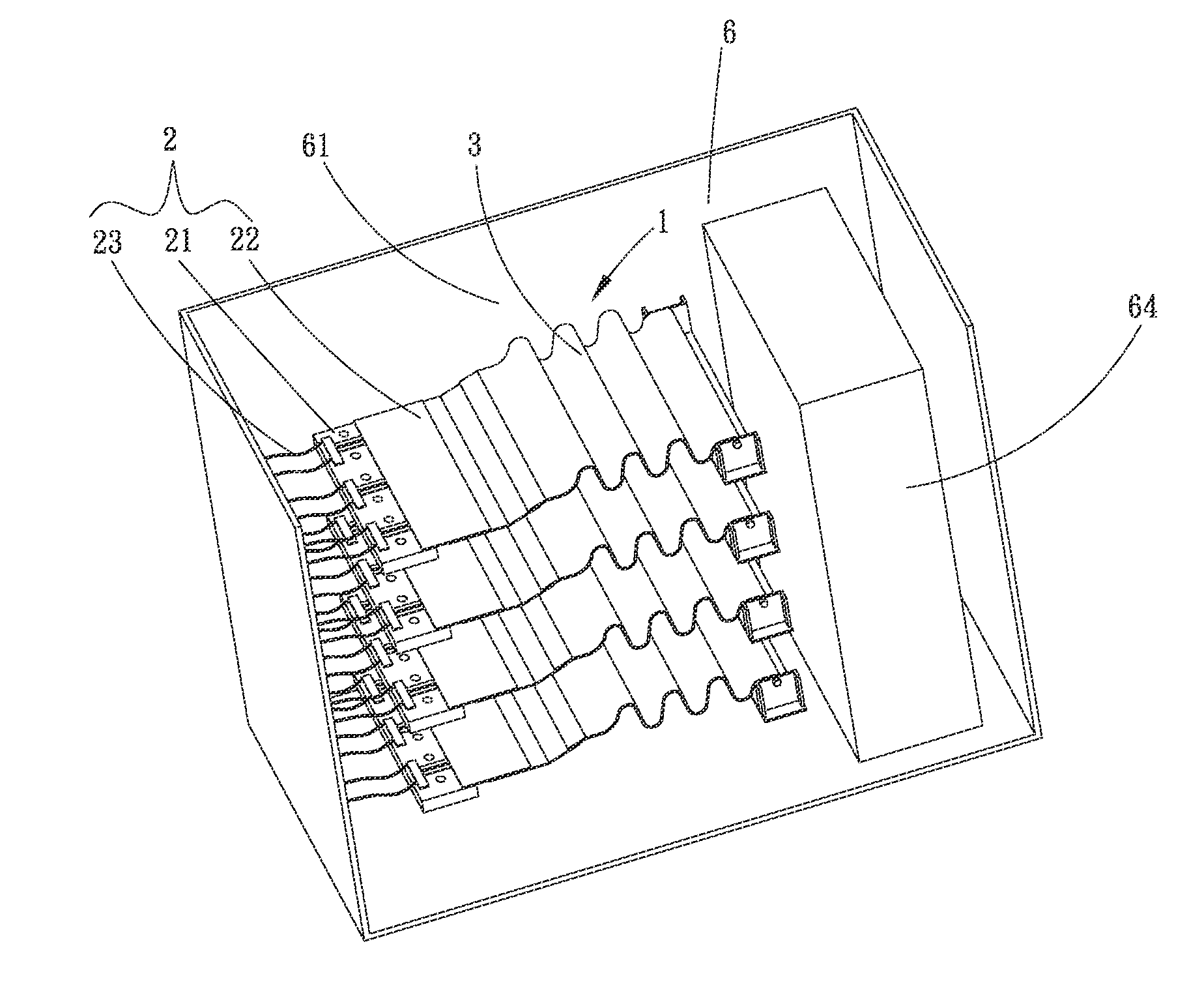
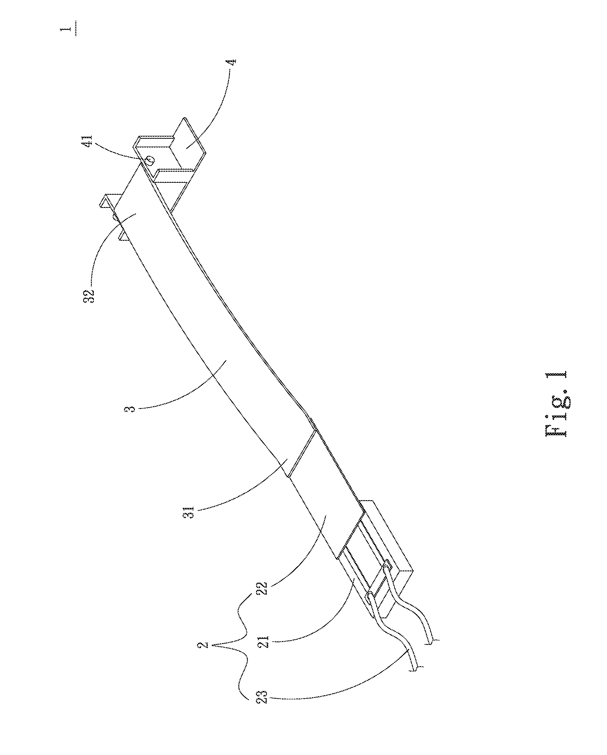
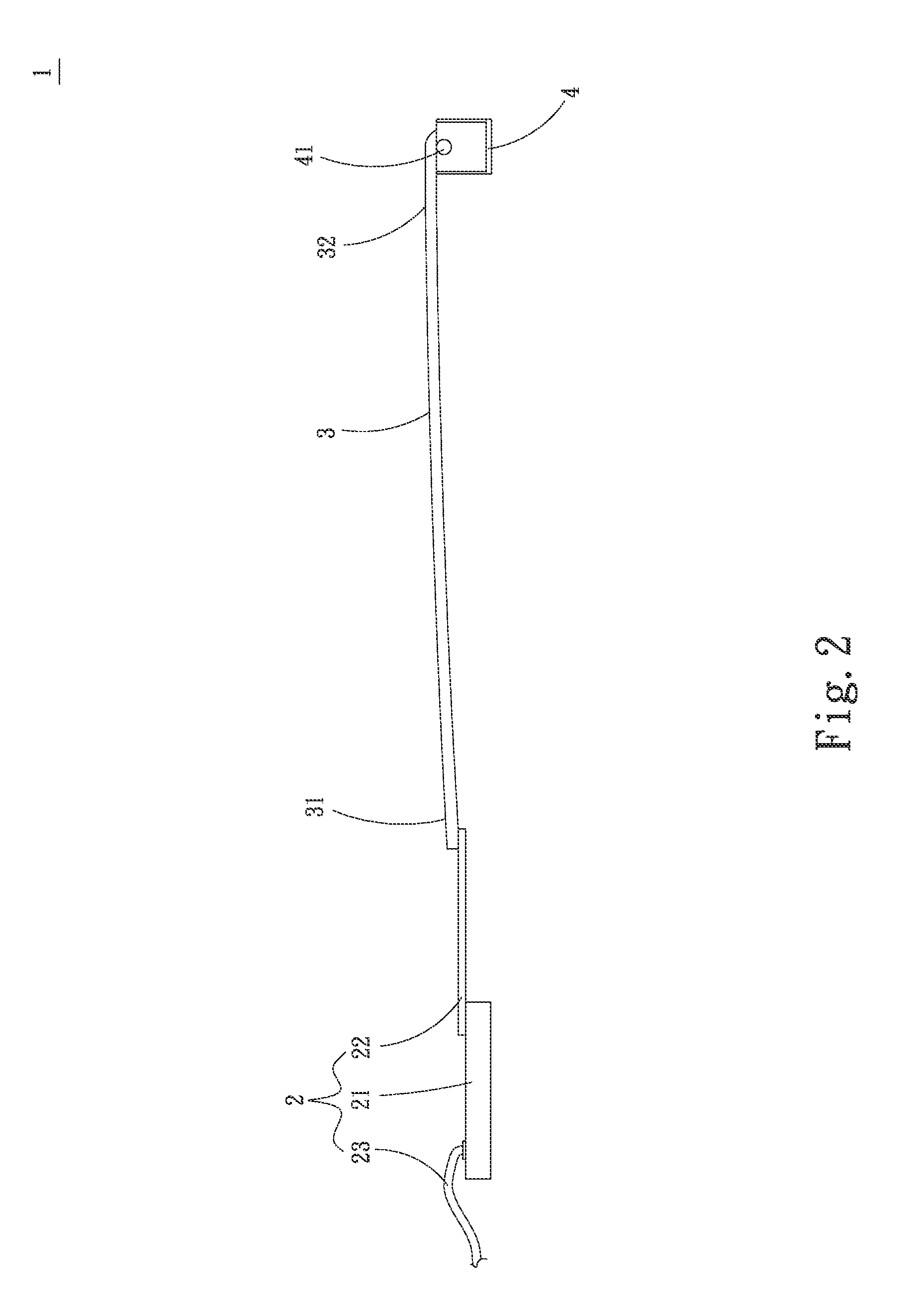
[0027]Please refer to FIGS. 1 and 2 that are assembled perspective and side views, respectively, of a heat dissipation device 1 according to a first preferred embodiment of the present invention. As shown, the heat dissipation device 1 in the first preferred embodiment includes an oscillation assembly 2, an air disturbing member 3, and at least one fixing seat 4.

[0028]The oscillation assembly 2 includes a base 21 and an oscillating member 22 provided on the base 21. The oscillation assembly 2 is adapted to generate a fixed-frequency oscillation. In the illustrated first preferred embodiment, the oscillation assembly 2 is a piezoelectric type oscillation assembly with the oscillating member 22 being a piezoelect...


PUM


Abstract

A heat dissipation device is arranged in an outer case of an electronic device, and includes an oscillation assembly, an air disturbing member and at least one fixing seat. The oscillation assembly includes a base and an oscillating member provided on the base; and the air disturbing member is connected at a first end to the oscillating member and at an opposite second end to the fixing seat. When an electric power is supplied to the oscillation assembly, the oscillating member is oscillated to thereby vibrate the first end of the air disturbing member, producing a continuous wave of the air disturbing member. The waving air disturbing member in turn disturbs air in the outer case, forcing the air toward a heat source and causing air convection in the outer case to enable largely upgraded heat dissipation efficiency of the electronic device.

Description

FIELD OF THE INVENTION[0001]The present invention relates to a heat dissipation device, and more particularly to a heat dissipation device that oscillates to produce a continuous wave of a member thereof for disturbing air and forming a relatively high static pressure of air, so as to force air toward a heat source for dissipating heat and enable largely upgraded heat dissipation efficiency.BACKGROUND OF THE INVENTION[0002]Following the rapid development in the electronic industrial fields in recent years, various electronic elements have largely upgraded performance to provide higher and higher operating and data processing speed. With the constantly increased operating speed of the chipset and the constantly increased number of chips inside the electronic elements, more heat is produced by the chips or the chipset during the operating thereof. The heat must be timely dissipated from the electronic elements to avoid largely lowered performance and reduced operating / data processing ...

Claims


Application Information

Patent Timeline
IPC IPC(8): H05K7/20
CPCH05K7/20136G06F1/203
Inventor CHANG, BOR-HAWWANG, CHUNG-SHU
Owner ASIA VITAL COMPONENTS SHENZHEN CO LTD
Why Eureka
Try Eureka