Electrostatic capacitive touch-sensitive panel for display device

a capacitive touch and display device technology, applied in the field of touch sensitive panels, can solve the problems of low touch accuracy in the edge regions, inability to cope with the recent demand for a narrow bezel,

Active Publication Date: 2015-03-05
LG DISPLAY CO LTD
View PDF5 Cites 32 Cited by
  • Summary
  • Abstract
  • Description
  • Claims
  • Application Information

AI Technical Summary

Problems solved by technology

However, such input devices as a keyboard, a mouse, etc require the user to learn to use them and take up space.
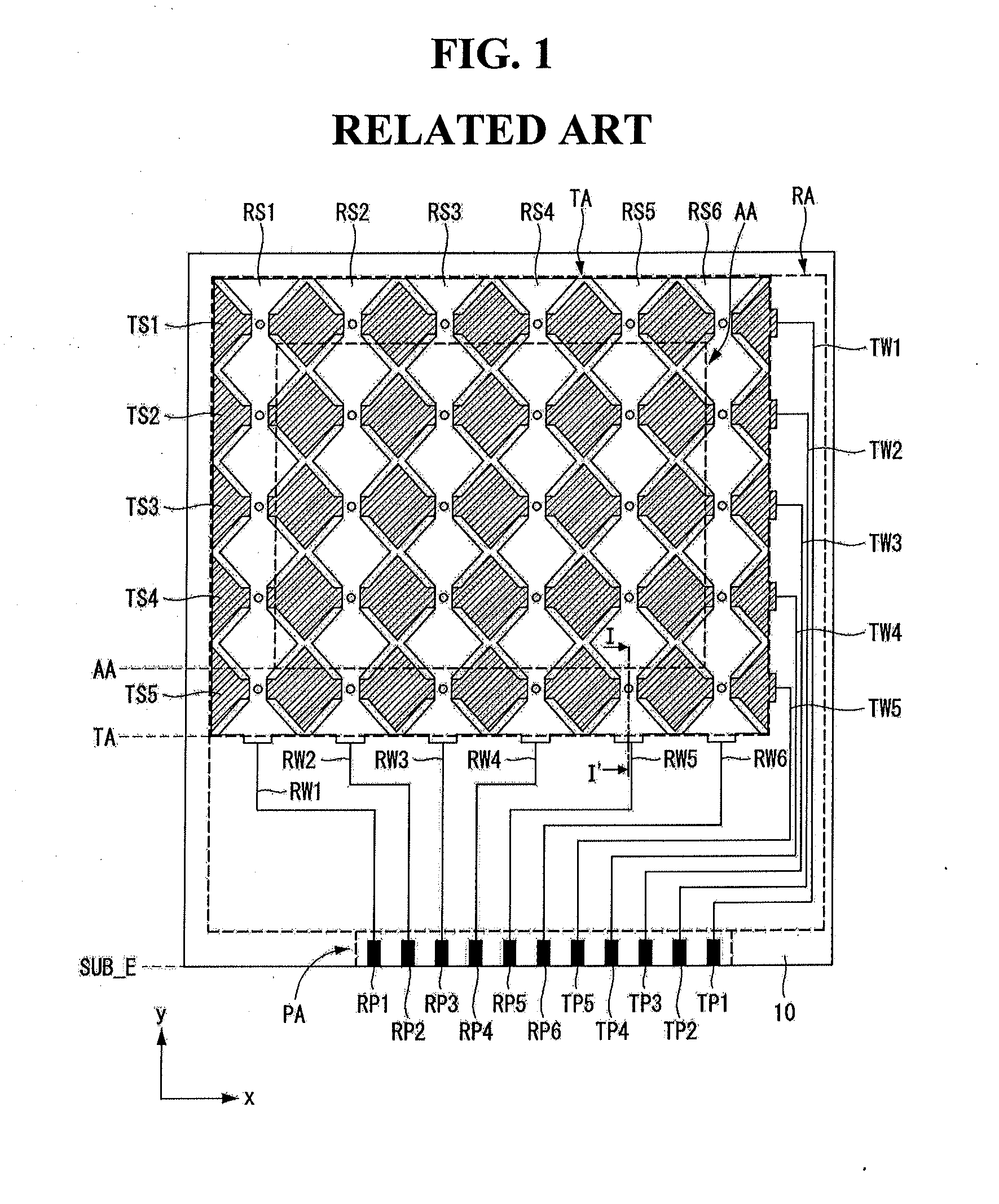
For this reason, the related art touch-sensitive panel has a wide bezel area (outside the active area AA) with no screen display, thus failing to cope with the recent demand for a narrow bezel.
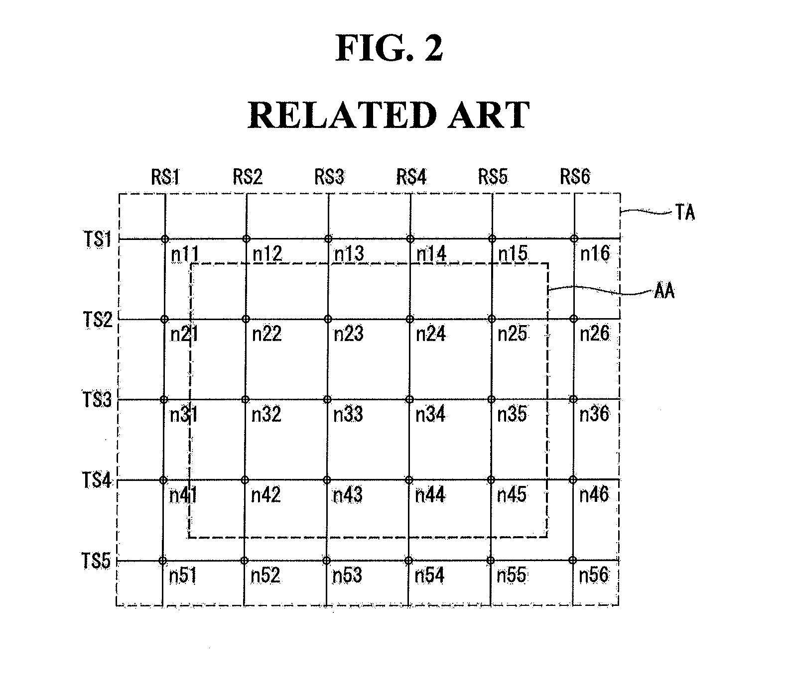
Moreover, the extension portions of the touch electrode lines TS1 to TS5 and RS1 to RS6 outside the active area AA are reduced, resulting in low touch accuracy on the edge regions.

Method used


Image

  • Electrostatic capacitive touch-sensitive panel for display device
  • Electrostatic capacitive touch-sensitive panel for display device
  • Electrostatic capacitive touch-sensitive panel for display device

Examples


first exemplary embodiment

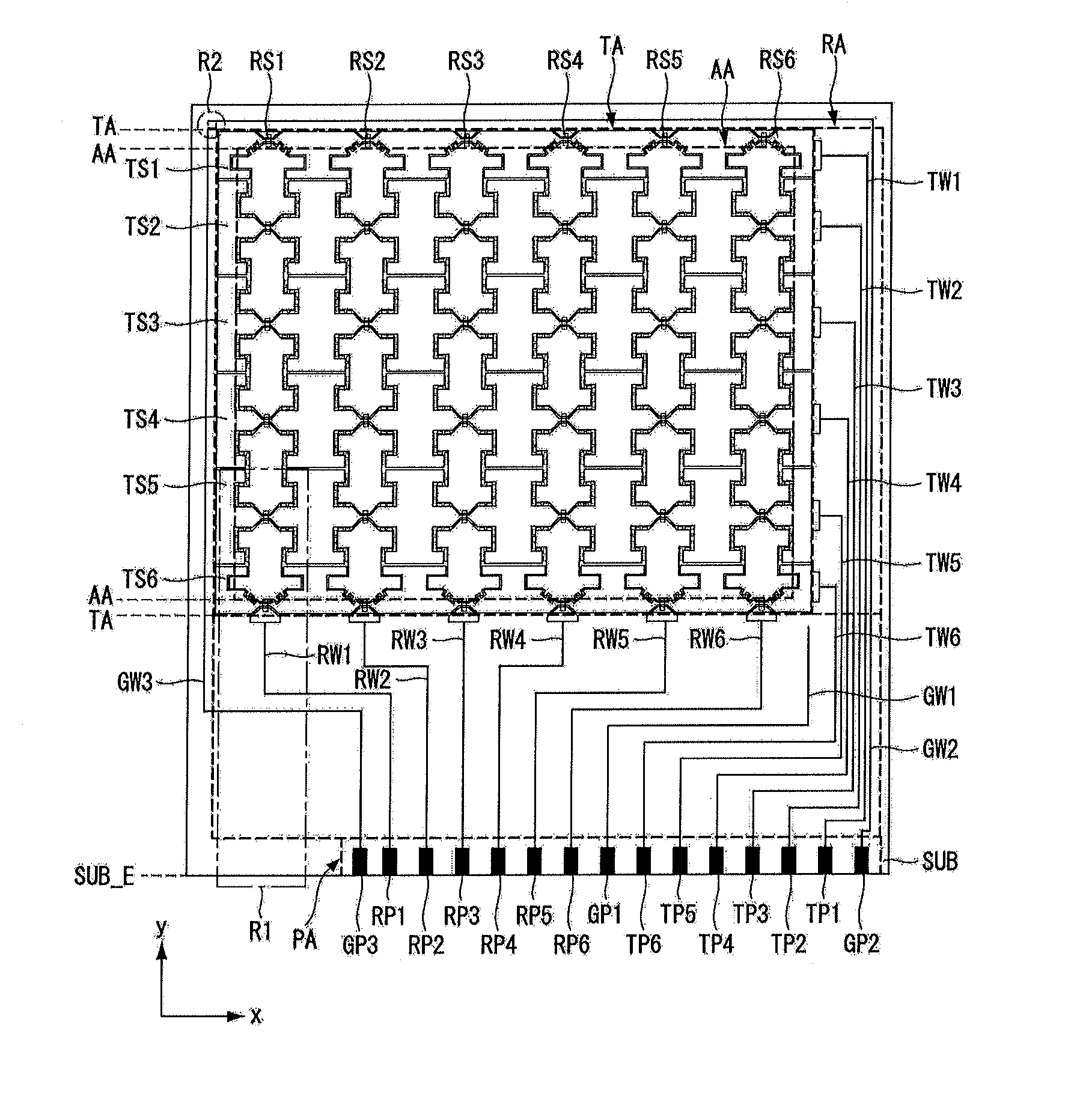
[0048]In this exemplary embodiment (first exemplary embodiment), the second touch electrode pattern Rx′ (hereinafter, ‘outermost second touch electrode pattern’) on the outermost part of the active area AA, i.e., closest to the boundary of the active area AA, has an asymmetrical portion with a different size and shape on the side closer to the boundary of the active area AA, as shown in FIG. 7a. The differently sized and shaped, asymmetrical portion of the outermost second touch electrode pattern has a zigzag portion. The first touch electrode pattern Tx corresponding to the zigzag portion of the outermost second touch electrode pattern Rx′ also has the corresponding zigzag portion. No dummy patterns are formed in the space between the zigzag portion of the first touch electrode pattern Tx and the zigzag portion of the outermost second touch electrode pattern Rx′ facing each other.

[0049]According to the first exemplary embodiment of the present invention, sensing nodes where signal ...

second exemplary embodiment

[0054]In this exemplary embodiment (second exemplary embodiment), like the first exemplary embodiment, the second touch electrode pattern Rx′ (hereinafter, ‘outermost second touch electrode pattern’) on the outermost part of the active area AA, i.e., closest to the boundary of the active area AA, has an asymmetrical portion with a different size and shape on the side closer to the boundary of the active area AA, as shown in FIG. 8a. The differently sized and shaped, asymmetrical portion of the outermost second touch electrode pattern Rx′ has a zigzag portion. The first touch electrode pattern Tx corresponding to the zigzag portion of the outermost second touch electrode pattern Rx′ also has the corresponding zigzag portion. No dummy patterns are formed in the space between the zigzag portion of the first touch electrode pattern Tx and the zigzag portion of the outermost second touch electrode pattern Rx′ facing each other.

[0055]According to the second exemplary embodiment of the pre...


PUM


Abstract

An electrostatic capacitive touch-sensitive panel has an active area; a touch electrode forming area; a routing wire forming area disposed; a plurality of first touch electrode lines disposed in the active area, with both ends extending to a plurality of electrode pattern extension regions; a plurality of second touch electrode lines disposed in the active area to cross the first direction so as to cross the first touch electrode lines without contact; a plurality of first routing wires connected to the plurality of first touch electrode lines, respectively; and a plurality of second routing wires connected to the plurality of second touch electrode lines, respectively. Each of the second touch electrode lines includes a plurality of second touch electrode patterns and a plurality of second connecting portions connecting neighboring second touch electrode patterns. The second touch electrode pattern has an asymmetrical portion.

Description

[0001]This application claims the benefit of priority under 35 U.S.C. §119(a) to Korean Patent Application No. 10-2013-0103483 filed on Aug. 29, 2013, which is incorporated by reference herein in its entirety.BACKGROUND[0002]1. Field[0003]This document relates to a touch-sensitive panel, and more particularly to an electrostatic capacitive touch sensitive panel, which offers increased touch performance by improving the touch accuracy on the edge regions of a touch-sensitive panel with a narrow bezel.[0004]2. Related Art[0005]Recently, various input devices such as a keyboard, a mouse, a trackball, a joystick, and a digitizer have been used to configure an interface between users and home appliances or various kinds of information communication equipments. However, such input devices as a keyboard, a mouse, etc require the user to learn to use them and take up space. Therefore, the demand for input devices that are convenient and easy to use and reduce erroneous operations is ever in...

Claims


Application Information

Patent Timeline
Patent Type & Authority Applications(United States)
IPC IPC(8): H03K17/96
CPCH03K17/9622H03K2217/960765H03K2217/960755H03K2017/9613G06F3/044G06F2203/04111G06F3/04164G06F3/0443G06F3/0446G06F3/0448G06F3/0416
Inventor KIM, DONGSUPLEE, JAEGYUN
Owner LG DISPLAY CO LTD
Why Eureka
Try Eureka