Touch liquid crystal display panel and device

A liquid crystal display panel and touch technology, applied in optics, instruments, electrical digital data processing, etc., can solve the problems affecting the touch accuracy of display devices and the large wiring area, so as to improve the touch accuracy and ensure Touch performance, area reduction effect

Active Publication Date: 2015-10-21
KUSN INFOVISION OPTOELECTRONICS
View PDF4 Cites 9 Cited by
  • Summary
  • Abstract
  • Description
  • Claims
  • Application Information

AI Technical Summary

Problems solved by technology

[0006] The present invention provides a touch-control liquid crystal display panel and a device to solve the problem that the existing touch-control liquid crystal display device has a large wiring area and affects the touch accuracy of the display device, etc.

Method used


Image

  • Touch liquid crystal display panel and device
  • Touch liquid crystal display panel and device
  • Touch liquid crystal display panel and device

Examples


Embodiment 1

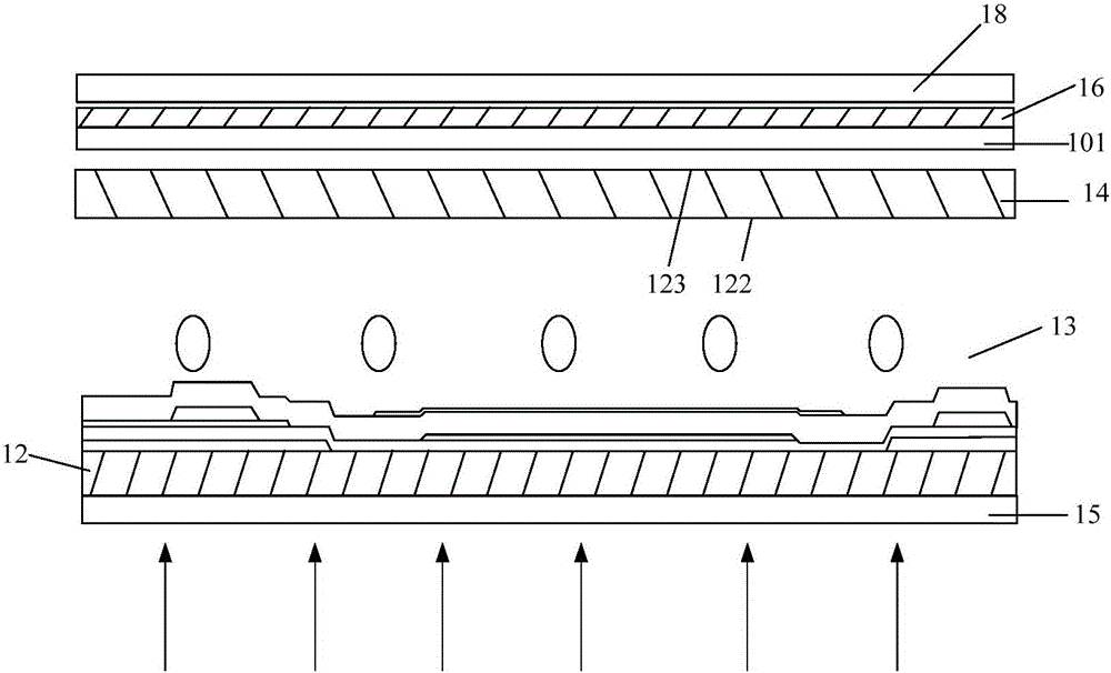
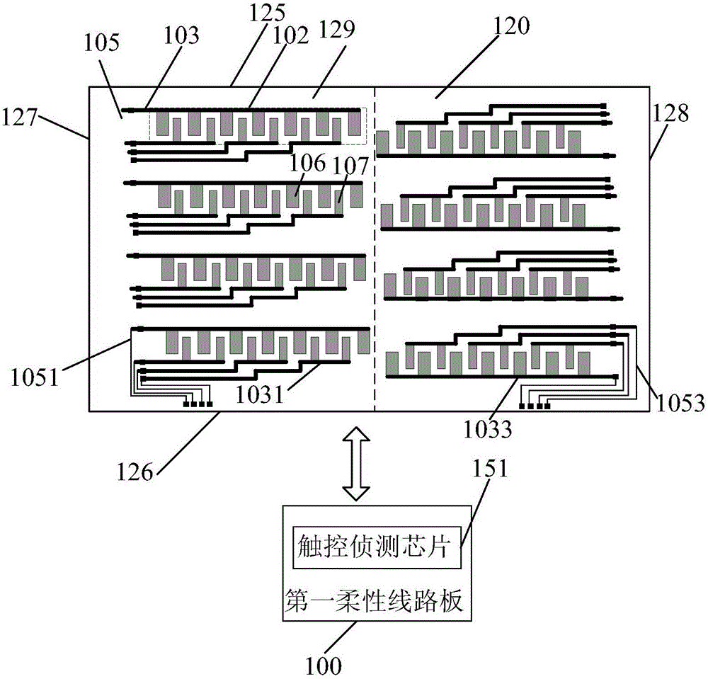
[0030] figure 2 A schematic cross-sectional structure diagram of the touch liquid crystal display panel in the first embodiment of the present invention is shown. image 3 It is a schematic diagram of the wiring structure of the touch layer in the first embodiment of the present invention. Please refer to figure 2 and image 3 , the touch display device 100 of this embodiment is an On-Cell touch liquid crystal display panel (Liquid Crystal Display, LCD). figure 2 The shown touch liquid crystal display panel includes: an array substrate 12, a color filter substrate 14, a lower polarizer 15 arranged below the array substrate 12, an upper polarizer 16 arranged above the color filter substrate 14, and an upper polarizer arranged on the The cover plate 18 above the upper polarizer 16 and the liquid crystal layer 13 between the array substrate 12 and the color filter substrate 14 .

[0031]Structures familiar to those skilled in the art, such as data lines, scan lines, thin f...

Embodiment 2

[0041] Please refer to Figure 5 , Figure 5 A schematic structural diagram of the touch liquid crystal display panel in the second embodiment of the present invention is shown. Figure 5 The structure shown is the same as image 3 The structure shown is the same except that, Figure 5 The touch liquid crystal display panel further includes a second flexible circuit board 501 and a third flexible circuit board 503 .

[0042] The second flexible circuit board 501 is close to the left end 127 of the color filter substrate 14 . The first peripheral wiring 1051 passes through the left end 127 of the color filter substrate 14 and then connects to the second flexible circuit board 501, and the second flexible circuit board 501 is connected to the touch detection chip 151 on the first flexible circuit board 100, namely The first peripheral wiring 1051 passes through the left end 127 of the color filter substrate 14 , the second flexible circuit board 501 and is connected to the t...

Embodiment 3

[0046] Please refer to Figure 6 , Figure 6 A schematic cross-sectional structure diagram of the touch liquid crystal display panel in the third embodiment of the present invention is shown. Figure 6 The structure shown is the same as figure 2 The shown touch liquid crystal display panel is similar, the difference is that the touch layer 101 is disposed on the first surface 122 of the color filter substrate 14 and faces to the side of the array substrate 12 . Wherein, in the embodiment of the present invention, the wiring structure of the touch layer 101 can be image 3 exactly the same in .

[0047] That is, the touch liquid crystal display panel provided in this embodiment is also provided on the first surface 122 of the color filter substrate 14 and facing the side of the array substrate 12 through the touch layer 101, so that the touch layer 101 can be adjusted according to actual needs. The position of 101 can be changed, and the application is flexible and conveni...


PUM


Abstract

The embodiment of the invention discloses a touch liquid crystal display panel and a device and belongs to the technical field of liquid crystal display, wherein the touch liquid crystal panel includes an array substrate; a color filter substrate which comprises a first region and a second region adjacent to the first region; a touch layer which is positioned on the color filter substrate and comprises a plurality of independent electrode units arranged in the first and second regions of the color filter substrate in a same layer, a plurality of leads connecting the electrode units out of the frame of the color filter substrate and peripheral wires which are positioned at the frame of the color filter substrate and correspond to the leads one by one, and the electrode units in the first and second regions are vertically and repeatedly arranged; a touch sensing chip which is electrically connected with the peripheral wires; a first flexible circuit board which is provided with a touch sensing chip. According to the embodiment of the invention, the touch accuracy of the liquid crystal display panel can be improved.

Description

technical field [0001] The present invention relates to the technical field of liquid crystal display, in particular to a touch liquid crystal display panel and a device. Background technique [0002] With the increasing development of science and technology, digital tools such as mobile phones, personal digital assistants, and notebook computers are developing in the direction of convenience, multi-function and beauty. Among them, the display screen is an indispensable human-machine communication interface in these devices. At present, Most mainstream display screens use liquid crystal display technology. On the other hand, with the rapid development and application of information technology, wireless mobile communication and information home appliances, in order to achieve more convenient, lighter and more humanized purposes, many information products have been input from traditional keyboards or mice and other devices. In order to use a touch panel (Touch Panel) as an in...

Claims


Application Information

Patent Timeline
Patent Type & Authority Applications(China)
IPC IPC(8): G06F3/041G02F1/1333G02F1/1343
Inventor 邱峰青李彬潘新叶
Owner KUSN INFOVISION OPTOELECTRONICS
Why Eureka
Try Eureka