
Single electrode layered capacitive touch-control device and panel module thereof

Inactive Publication Date: 2014-09-04
ILI TECHNOLOGY CORPORATION
View PDF6 Cites 7 Cited by
  • Summary
  • Abstract
  • Description
  • Claims
  • Application Information

AI Technical Summary

Benefits of technology

The patent text describes a touch-control device with electrodes arranged in a way that improves edge touch accuracy and capacitance distribution. The device uses a single electrode layered capacitive touch-control system. The first electrodes and second electrodes are located at opposite sides of each coupling electrode at each touch-control segment, which ensures a uniform arrangement of the first conductive lines on the substrate and enhances edge touch accuracy. The portions of the transparent electrode layer on adjacent touch-control segments are configured in mirror symmetry arrangement. This prevents electric coupling between the first and second conductive lines and improves the panel module's capacitance distribution.

Problems solved by technology

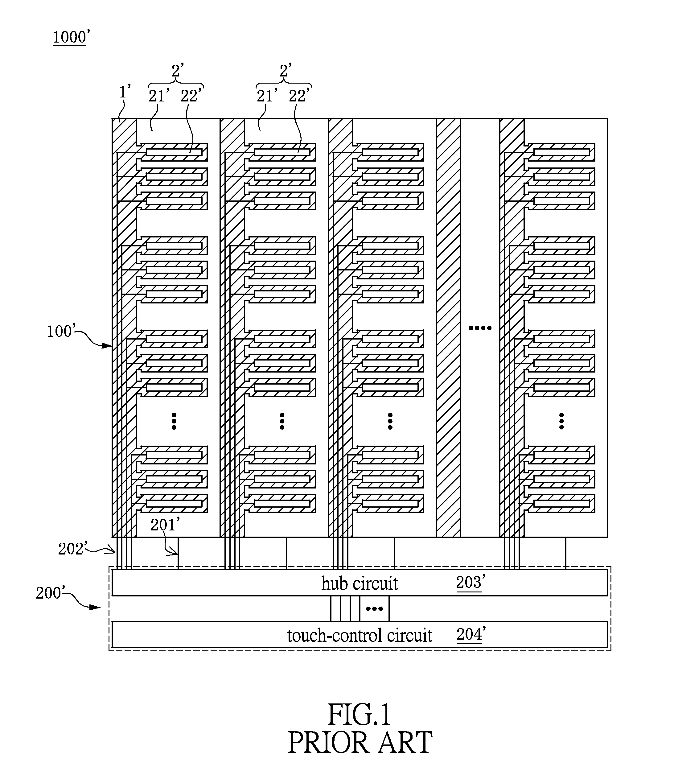
However, conventional single electrode layered capacitive touch-control device has some problems.

Method used


Image

  • Single electrode layered capacitive touch-control device and panel module thereof
  • Single electrode layered capacitive touch-control device and panel module thereof
  • Single electrode layered capacitive touch-control device and panel module thereof

Examples


first embodiment

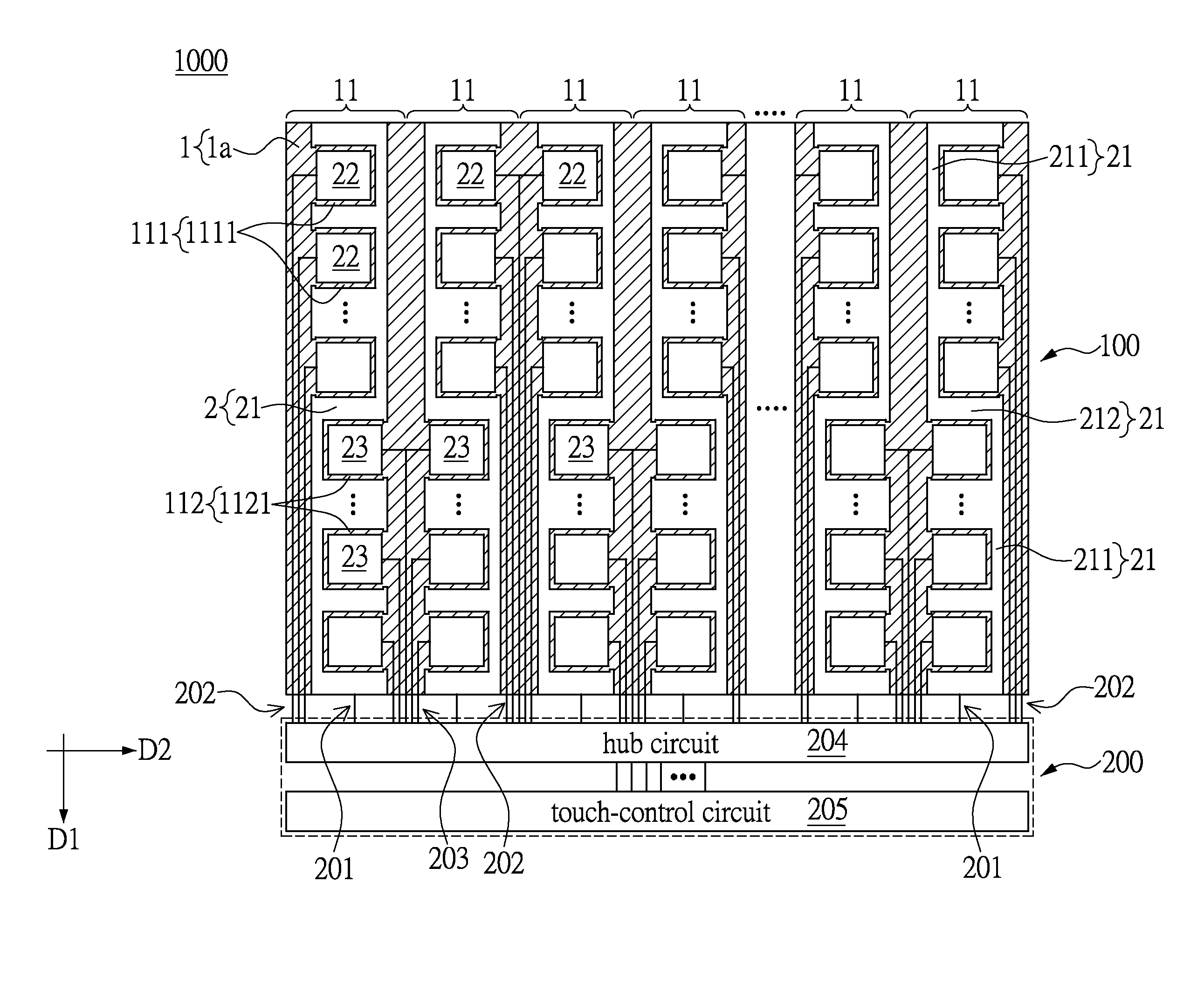
[0025]Please refer to FIGS. 2 and 3, which show a first embodiment of the instant disclosure. The instant embodiment provides a single electrode layered capacitive touch-control device 1000 including a panel module 100 and a circuit module 200. The panel module 100 has a substrate 1 and a transparent electrode layer 2 disposed on the substrate 1.

[0026]The substrate 1 has an inner surface 1a and an opposite outer surface 1b. The substrate 1 is configured to protect and carry each element disposed on the inner surface 1a, and the outer surface 1b is configured to provide a touch-control interface by a finger or a touch-control pen. A functional layer (e.g., anti-reflective layer or anti-dirt layer) can be coating on the outer surface 1b of the substrate 1 according to users' demand. The substrate 1 is a transparent plate, which is made of glass having a heat resistance of at least 1000° C., but the material of the substrate 1 is not limited to the instant embodiment. For example, the ...

second embodiment

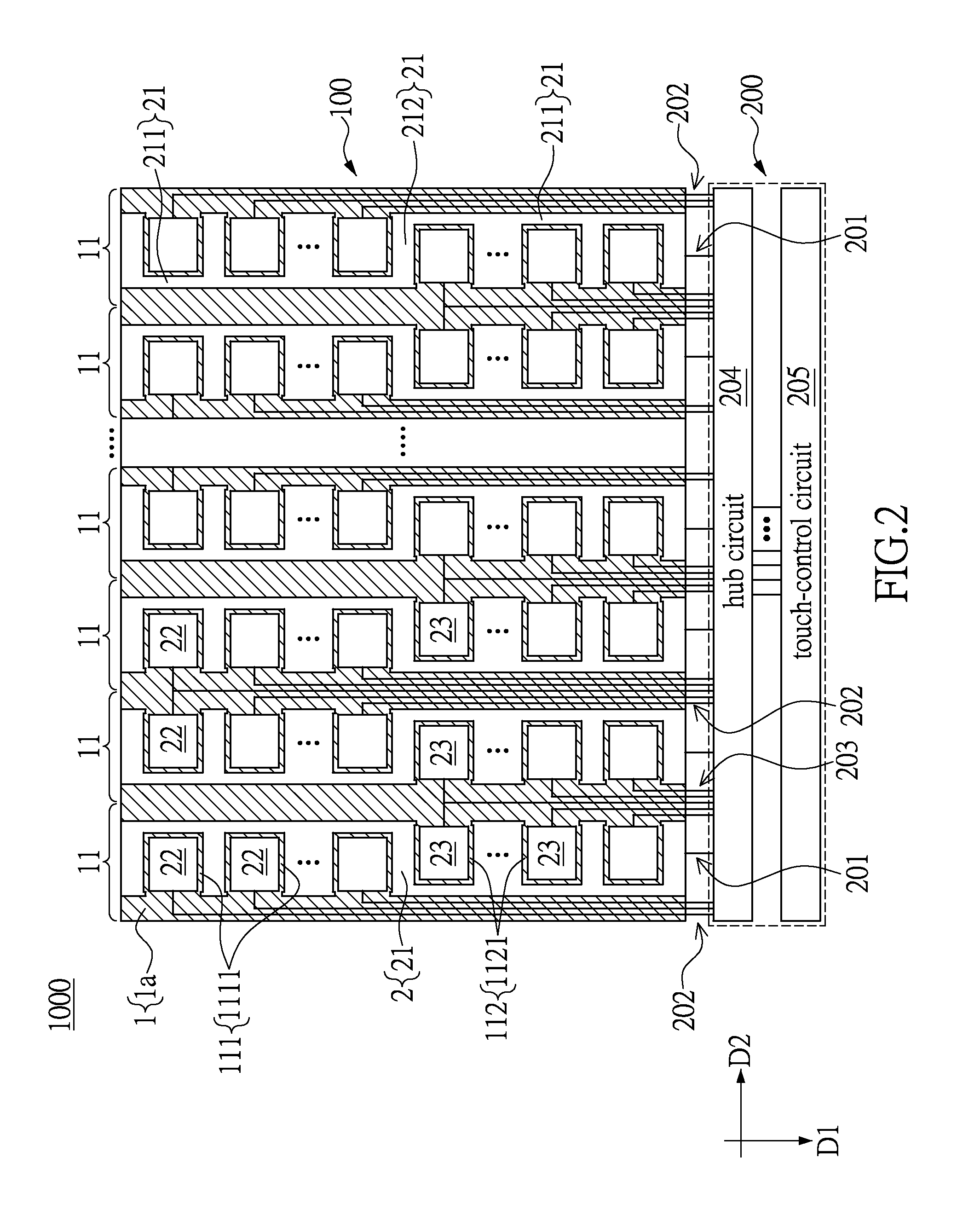
[0053]Please refer to FIGS. 6 and 7, which show a second embodiment of the instant disclosure. The instant embodiment is similar to the first embodiment, and the identical features do not state again. The difference between the instant embodiment and the first embodiment is the construction of the transparent electrode layer 2.

[0054]At each touch-control segment 11, the first electrode 22 and the second electrode 23 are alternatingly arranged along the first direction D1. As shown in FIG. 6, each coupling electrode 21 has a plurality of longitudinal portions 211 and a plurality of transversal portions 212, in which the longitudinal portions 211 are staggeredly arranged in two columns and each column is parallel to the first direction D1, and the transversal portions 212 are respectively parallel to the second direction D2. The adjacent ends of each two adjacent longitudinal portions 211 are coupled by two opposite ends of one transversal portion 212, so that the coupling electrode 2...


PUM


Abstract

A panel module includes a substrate and a transparent electrode layer disposed on the substrate. The inner surface of the substrate has a plurality of touch-control segments. The transparent electrode layer of each touch-control segment has a coupling electrode, a plurality of first electrodes, and a plurality of second electrodes, wherein the coupling electrode, the first electrodes, and the second electrodes are arranged in an interval and insulting with each other. Each coupling electrode is separating the corresponding touch-control segment into a first-side region and a second-side region, wherein the first-side region and the second-side region are arranged on two opposite sides of the coupling electrode, the first electrodes are disposed on the first-side region, and the second electrodes are disposed on the second-side region. A portion of the transparent electrode layer disposed on any two adjacent touch-control segments are configured in a mirror symmetry arrangement.

Description

BACKGROUND OF THE INVENTION[0001]1. Field of the Invention[0002]The instant disclosure relates to a touch-control device; more particularly, to a single electrode layered capacitive touch-control device and a panel module thereof.[0003]2. Description of Related Art[0004]With the advancement of technology, the electronic information products not only progress toward a direction of being lighter and thinner, but also provide a friendlier human-machine interface so as to bring the convenience for the user. The human-machine interface includes an output interface and an input interface and the human-machine interface acts as a bridge between the user and electronic information product. The liquid crystal panel possesses some advantages, such as slim and light, such that it is easy for user to carry the liquid crystal panel, and the liquid crystal panel gradually replaces the cathode ray tube (CRT) commonly used for traditional output interface. With the use of liquid crystal panel, the ...

Claims


Application Information

Patent Timeline
IPC IPC(8): G06F3/044
CPCG06F3/044G06F3/04164G06F3/0443G06F3/0448
Inventor LEE, PEI-YUCHEN, HANG-KAI
Owner ILI TECHNOLOGY CORPORATION
Learn More