Flexible organic electroluminescent device and method for fabricating the same

a flexible, organic technology, applied in the direction of solid-state devices, semiconductor devices, thermoelectric devices, etc., can solve the problems of defective screen, defective driving, etc., and achieve the effect of minimizing damage to the flexible organic electroluminescent devi

Active Publication Date: 2015-03-05
LG DISPLAY CO LTD
View PDF9 Cites 128 Cited by
  • Summary
  • Abstract
  • Description
  • Claims
  • Application Information

AI Technical Summary

Benefits of technology

[0042]An advantage of invention is to provide a flexible organic electroluminescent device in which line hole patterns are formed on surfaces of a plurality of inorganic layers positioned in a pad region to which a FPCB is connected, that is weak due to repeated bending and spreading when the organic electroluminescent device is fabricated, in order to redirect a path of cracks so that the cracks do not spread to the interior of the device. Thus, damage to the flexible organic electroluminescent device is minimized.
[0045]According to the flexible organic electroluminescent device and the method for fabricating the same according to the present embodiments, line hole patterns are formed in surfaces of a plurality of inorganic layers, i.e., the gate insulating layer, the interlayer insulating layer, and the passivation layer, positioned in a weak region, i.e., a pad region to which an FPCB is connected, or a non-display region including the pad region due to repeated bending and in spreading when the organic electroluminescent device is fabricated. Thus, a path of cracks is redirected and prevented from spreading to the interior of the device, which minimizes damage to the flexible organic electroluminescent device.
[0046]In particular, because a plurality of line hole patterns are formed in a weak point that is adjacent to a scribe line to redirect a path of line damage and cracks in the weak point, panel line cracks, as a critical point, can be prevented.
[0047]Further, a trimming cutting is applied on trimming lines defined at edges of upper and lower of the pad region of a panel in fabricating of the flexible organic electroluminescent device because a curve hole pattern is formed at the upper and lower of the pad region to surround the trimming line of the pad region so that a path of cracks is redirected and prevented from spreading to the interior of the device; thereby minimizing damage to the flexible organic electroluminescent device.
[0048]Further, in a case that a trimming cutting is applied on trimming lines defined at edges of upper and lower of the non-display region located opposite to the pad region including the edges of the upper and lower of the pad region in fabricating of the flexible organic electroluminescent device, because a line hole pattern extended from the curve hole pattern is further formed at the non-display region including the pad region to be surround the trimming line and the display region, so that a path of cracks is redirected and prevented from spreading to the interior of the device; thereby minimizing damage to the flexible organic electroluminescent device.

Problems solved by technology

Also, the cracks increase during a follow-up process to interfere with a signal line of a panel, which leads to defective driving and a defective screen.

Method used


Image

  • Flexible organic electroluminescent device and method for fabricating the same
  • Flexible organic electroluminescent device and method for fabricating the same
  • Flexible organic electroluminescent device and method for fabricating the same

Examples


Embodiment Construction

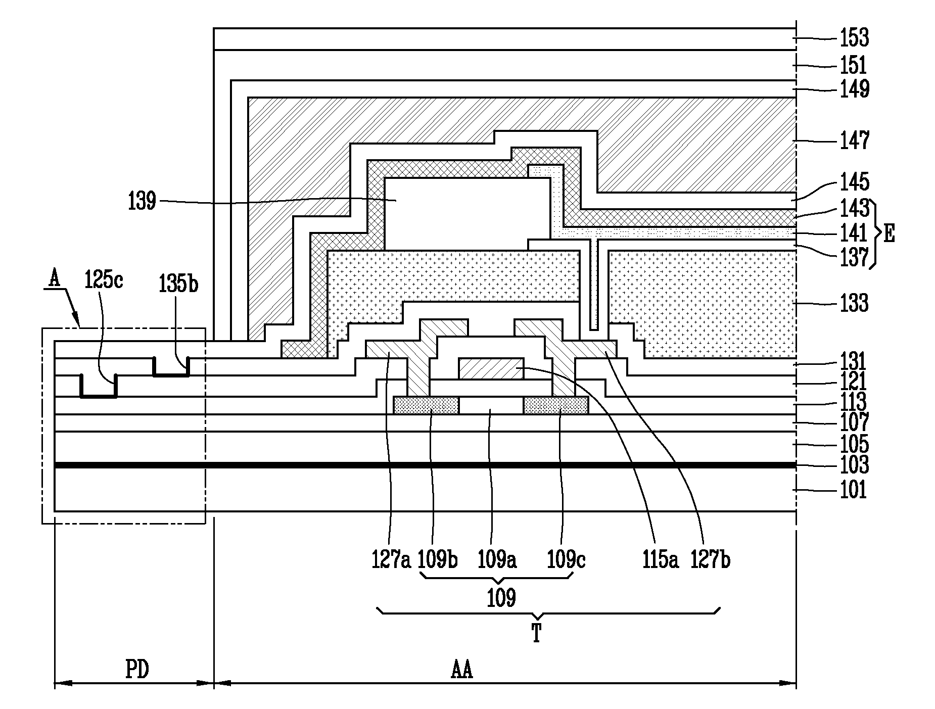
[0063]A flexible organic electroluminescent device according to embodiments of the present invention will be described in detail with reference to the accompanying drawings.

[0064]Hereinafter, embodiments will be described in detail with reference to the accompanying drawings such that they can be easily practiced by those skilled in the art to which the present invention pertains. In describing the present invention, if a detailed explanation for a related known function or construction is considered to unnecessarily divert the gist of the present invention, such explanation will be omitted but would be understood by those skilled in the art. Also, similar reference numerals are used for the similar parts throughout the specification.

[0065]The flexible organic electroluminescent device according to an embodiment of the present invention may be divided into a top emission type device and a bottom emission type device based upon a direction in which emitted light is transmitted. Herei...


PUM


Abstract

Provided is a flexible organic electroluminescent device and a method for fabricating the same. In the flexible electroluminescent device, line hole patterns are formed on surfaces of a plurality of inorganic layers positioned in a pad region in which a flexible printed circuit board is connected to prevent a path of cracks caused by repeated bending and spreading of the organic electroluminescent device from spreading to the interior of the device.

Description

CROSS-REFERENCE TO RELATED APPLICATIONS[0001]This application claims the benefit of the Korean Patent Application No. 10-2013-0104342 filed on Aug. 30, 2013, and Korean Patent Application No. 10-2013-0149446, filed on Dec. 3, 2013, which are hereby incorporated by reference for all purposes as if fully set forth herein.BACKGROUND OF THE INVENTION[0002]1. Field of the Invention[0003]The present invention relates to an organic electroluminescent device (or an organic light emitting display device. More particularly, the present invention relates to a flexible organic electroluminescent device capable of minimizing the generation of cracks by a step portion with a line hole formed in a pad region in which cracks are readily generated, or a non-display region including the pad region, and a method for fabricating the same.[0004]2. Discussion of the Related Art[0005]An organic electroluminescent device, one of flat panel displays (FPDs), has a high degree of luminance and low operational...

Claims


Application Information

Patent Timeline
Patent Type & Authority Applications(United States)
IPC IPC(8): H01L27/32H01L51/56
CPCH01L51/56H01L27/3258Y02E10/549H10K59/124H10K77/111H10K50/8426H10K50/844H10K50/868H10K59/1201
Inventor KIM, SU HOKIM, SANG BAEJEON, JUN TAELEE, YONG SAM
Owner LG DISPLAY CO LTD
Why Eureka
Try Eureka