Antenna module and antenna thereof

a technology of antenna module and antenna, applied in the direction of antenna details, electrically short antennas, antennas, etc., can solve the problems of affecting the performance of antennas, antenna operation failure at the operating frequency, and not allowing the dimension of ground elements to be significantly reduced, so as to minimize the size of antennas and optimize antenna arrangements

Active Publication Date: 2015-03-05
UNIVERSAL SCIENTIFIC INDUSTRIAL (SHANGHAI) CO LTD +1
View PDF3 Cites 8 Cited by
  • Summary
  • Abstract
  • Description
  • Claims
  • Application Information

AI Technical Summary

Benefits of technology

[0010]The present invention has been accomplished under the circumstances in view. It is the main object of the present invention to provide an antenna module and an antenna thereof, which keeps the feeding signal inputting direction and outputting direction in a perpendicular relationship, obtaining optimal antenna arrangement and minimizing the size of the antenna.

Problems solved by technology

However, this conventional arrangement does not allow the dimension of the ground element to be significantly reduced.
Reducing the dimension will cause the ground element to lose its inductance characteristic, leading to antenna operation failure at the operating frequency.
Further, because the radiating elements have the same line width, a magnetic flux leakage can occur at every turning corner of each radiating element, affecting the performance of the antenna.
However, the pins of the electrical connector have a specific length and cannot be shortened.
Thus, during a high-frequency application, the pins can induce an extra inductance effect, causing the impedance of the antenna unable to obtain optimal impedance matching.

Method used


Image

  • Antenna module and antenna thereof
  • Antenna module and antenna thereof
  • Antenna module and antenna thereof

Examples


Embodiment Construction

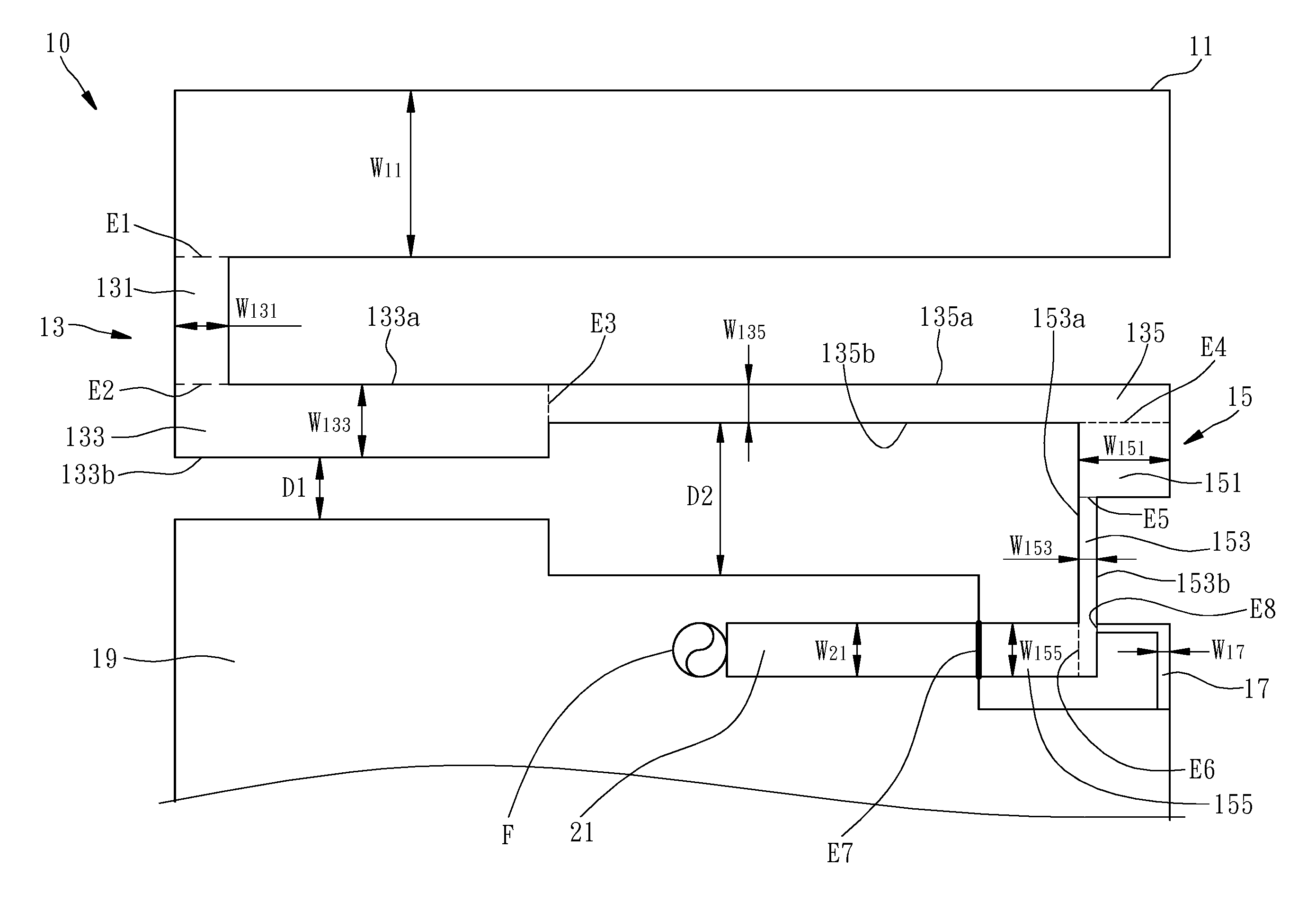
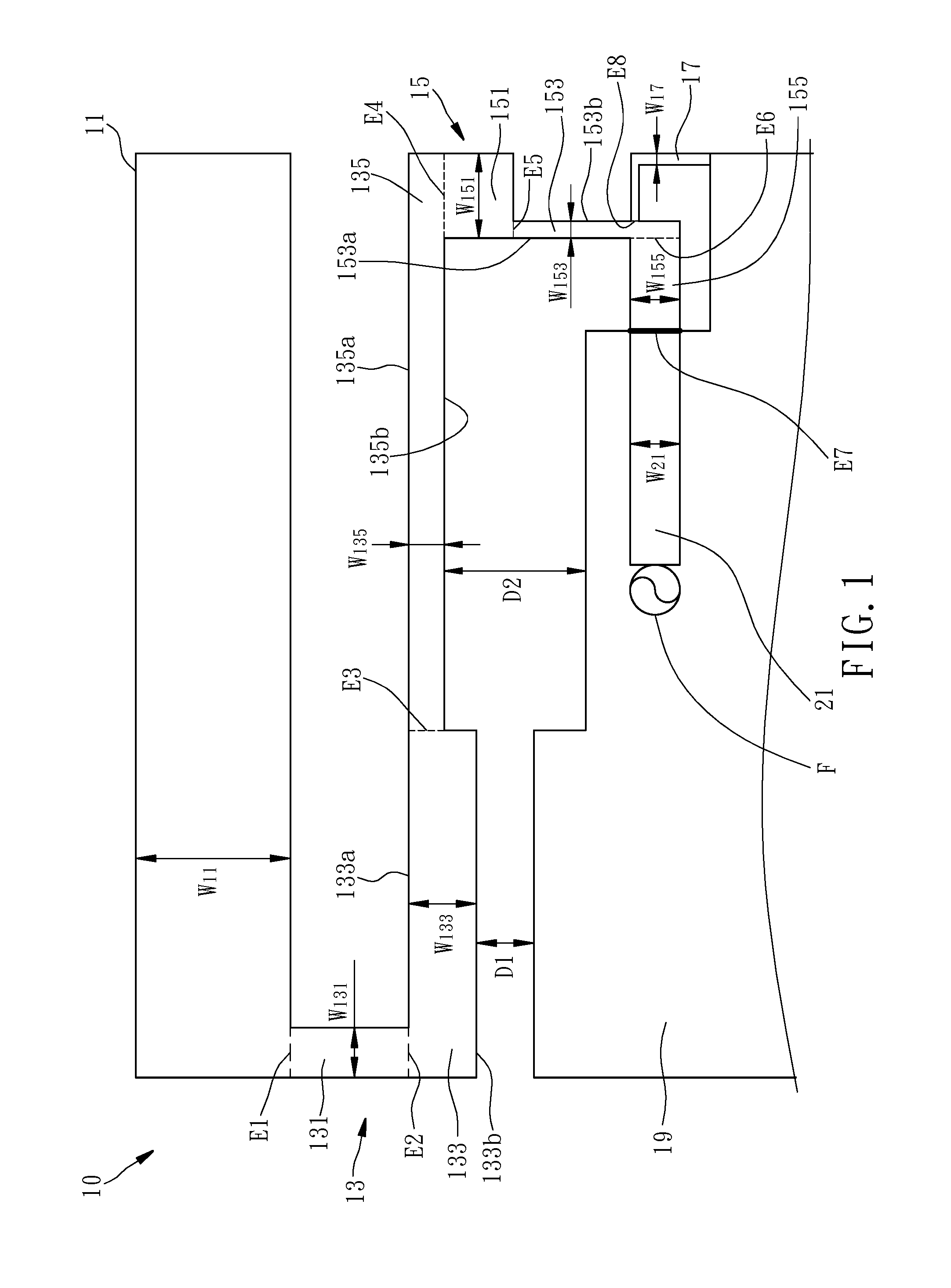
[0017]To clearly illustrate the technical features of the present invention, the size of the antenna in accordance with the preferred embodiment of present invention is based on the operating frequency of 2.4 GHz. In practice, however, the antenna varies in size subject to change of the operating frequency, for example, the antenna dimension will be relatively smaller than the preferred embodiment if it operates around 60 GHz, therefore, the antenna of the present invention is not limited to the operating frequency of 2.4 GHz.

[0018]Referring to FIG. 1, an antenna in accordance with the present invention is shown. The antenna 10 is a one-piece member, comprising a first radiation element 11 a second radiation element 13, a third radiation element 15, a short-circuit portion 17, a grounding plane 19 and a transmission unit 21. In order to clearly illustrate the technical features of the present invention, broken lines are used to divide the radiation elements, however, these broken li...


PUM


Abstract

The present invention provides an antenna module and an antenna thereof. The antenna includes a first radiation element, a second radiation element, a third radiation element, and a short-circuit portion. The second radiation element has one end connected with the first radiation element. The third radiation element connected with the other end of the second radiation element, and includes a first connection section, a second connection section, and a third connection section. The first connection section is perpendicular to the second radiation element. The second connection section connected with the first connection section. The third connection section is connected with the second connection section and located at an internal side of the second connection section. The short-circuit portion connected with the second connection section and located at an external side of the second connection portion.

Description

BACKGROUND OF THE INVENTION[0001]1. Field of the Invention[0002]The present invention relates to antenna technology, and more particularly, to an antenna module and an antenna thereof.[0003]2. Description of the Related Art[0004]With the increase of additional functions in handheld communication devices (such as, smart phone, digital camera, tablet computer and PDA, etc.), circuit modules corresponding to these additional functions are compressed into a small size that can be placed in a predetermined configuration space (the inside of a handheld communication device). Thus, miniaturization has become the important developing of circuit modules.[0005]Following the aforesaid trend toward miniaturization in circuit module technology, antenna modules for handheld communication products must be small-sized. To reduce the size of an antenna module, it is normally to limit the configuration space of the antenna module at first, and then to design the antenna size and the antenna drive cir...

Claims


Application Information

Patent Timeline
Patent Type & Authority Applications(United States)
IPC IPC(8): H01Q1/36
CPCH01Q1/36H01Q9/0421H01Q1/243
Inventor CHEN, HSIN-HONGSHIH, JUI-KUNCHIANG, CHUNG-HSIN
Owner UNIVERSAL SCIENTIFIC INDUSTRIAL (SHANGHAI) CO LTD
Why Eureka
Try Eureka