Dual-band multi-mode array antenna

a multi-mode array and antenna technology, applied in the field of patch antennas, can solve the problems of unsuitable conventional antenna structures and a lot of inconvenience, and achieve the effect of increasing the pointing natur

Inactive Publication Date: 2007-03-22
SMARANT TELECOM
View PDF8 Cites 13 Cited by
  • Summary
  • Abstract
  • Description
  • Claims
  • Application Information

AI Technical Summary

Benefits of technology

[0015] Besides, the disclosed dual band multi-mode array antenna further includes a reflective plate, which is provided on both sides of the conductive s

Problems solved by technology

This causes a lot of inconvenience.
The conventional a

Method used


Image

  • Dual-band multi-mode array antenna
  • Dual-band multi-mode array antenna
  • Dual-band multi-mode array antenna

Examples


Embodiment Construction

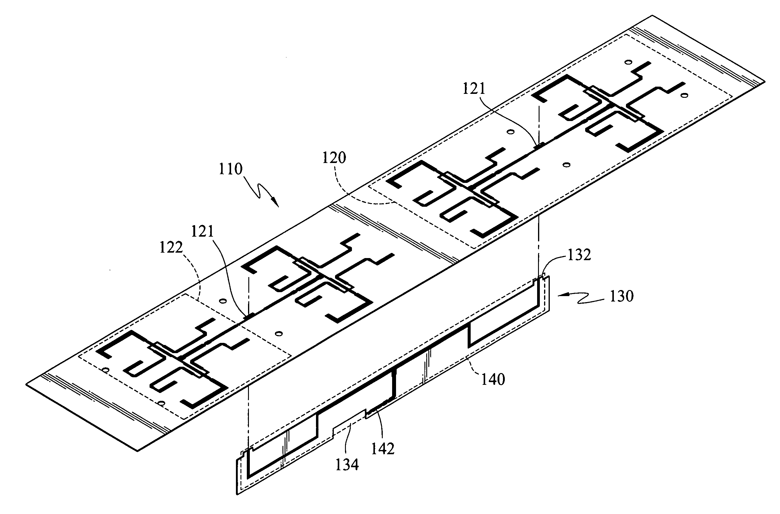
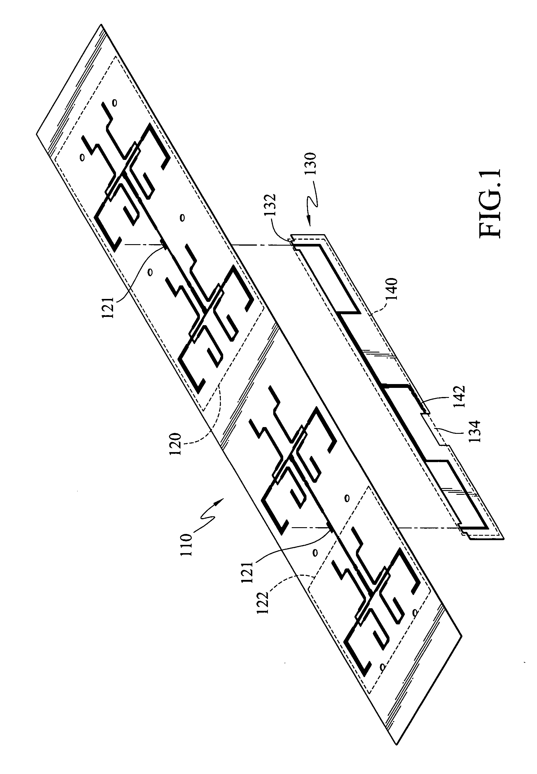
[0029] The conventional array antenna has the antenna pattern and the feeding network pattern formed on the same surface (i.e., on the same substrate). In this invention, the antenna pattern and the feeding network pattern are disposed separately on individual substrates. The two substrates are connected in a crossing way to minimize the planar size of the antenna structure.

[0030] As shown in FIG. 1, the dual-band multi-mode array antenna according to the first embodiment of the invention includes: an antenna substrate 110 and a conductive substrate 130.

[0031] The antenna substrate 110 is coupled to the conductive substrate 130 at an angle. The angle is preferably about 90 degrees. That is, the two substrates are roughly perpendicular to each other.

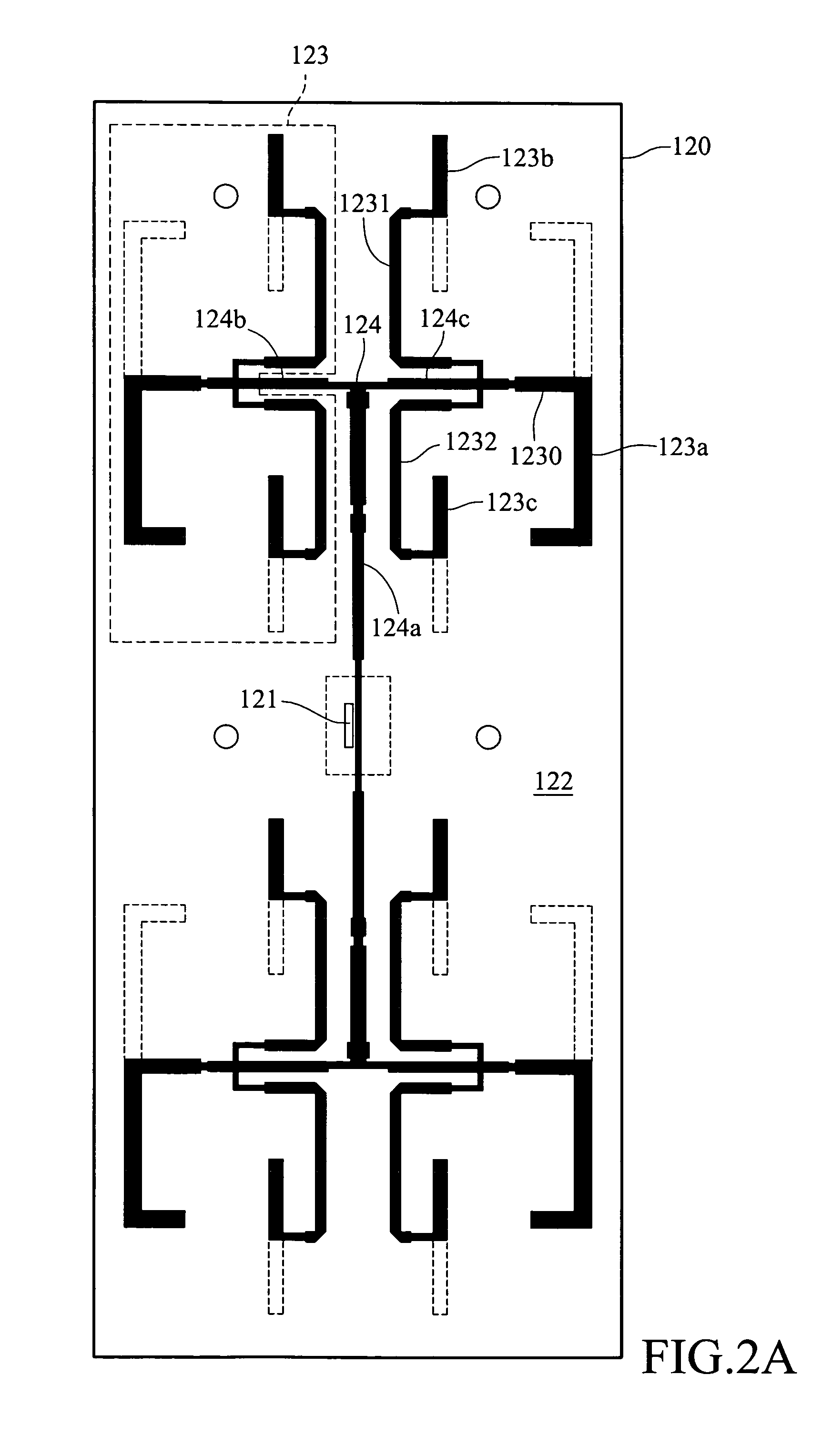
[0032] The antenna substrate 110 is provided with a microstrip trace pattern to form a plurality of antenna units 120. Each of the antenna units 120 has a feeding via 121, formed along a line.

[0033] One surface of the conductive subst...


PUM


Abstract

A dual-band multi-mode array antenna is provided, including an antenna substrate with antenna units each of which having a feeding via; and a conductive substrate connected to the antenna substrate to form an angle in between. The conductive substrate has a symmetric feeding network disposed on a surface of the conductive substrate; and a first ground portion disposed on another surface of the conductive substrate. The symmetric feeding network and the first ground portion are electrically coupled to each of the antenna units through the feeding vias. Moreover, the antenna units are electrically coupled in parallel.

Description

BACKGROUND [0001] 1. Field of Invention [0002] The invention relates to a patch antenna and, in particular, to a double-band multi-mode array antenna. [0003] 2. Related Art [0004] The rapid development in wireless communication technology and semiconductor processes in recent years have brought us wireless communication and satellite communication networks, such as satellite positioning systems, direct broadcasting satellites (DBS), mobile satellites (MSAT), wireless phones, wireless area network systems, wireless subscriber exchange machines, wireless area pagers, etc. The wireless communication system is mainly comprised of a transceiver and an antenna. The antenna is the bridge to transceiving electromagnetic signals in air and an indispensable device in the communication system. Currently, the antenna is preferred to be made using printed circuits. It has the advantages of easy production and low cost. [0005] A communication standard commonly used in wireless communications is I...

Claims


Application Information

Patent Timeline
IPC IPC(8): H01Q21/08
CPCH01Q21/0075H01Q21/062H01Q5/48H01Q21/30H01Q5/42H01Q21/08
Inventor WU, CHUNG-HANSONG, JIA-JIU
Owner SMARANT TELECOM
Why Eureka
Try Eureka