
Systems and methods for adjusting frequencies and currents based on load conditions of power conversion systems

a power conversion system and load condition technology, applied in the field of integrated circuits, can solve the problems that the power conversion system b>100/b> often has some problems in operation

Active Publication Date: 2015-03-05
ON BRIGHT ELECTRONICS SHANGHAI
View PDF6 Cites 57 Cited by
  • Summary
  • Abstract
  • Description
  • Claims
  • Application Information

AI Technical Summary

Benefits of technology

The technical effect of this patent is to provide improvements for an electronic device by incorporating certain components and methods. This improvement could lead to better performance, reliability, durability, efficiency, etc.

Problems solved by technology

This patent describes a problem faced by traditional power conversion systems - namely, noise during low load or standalone operations. These issues are caused because the frequency and current settings cannot adapt accordingly due to fixed hardware configurations. The technical solution presented involves integrating advanced technology into these systems to allow them to automatically adjust their own frequencies and currents based on actual loads.

Method used


Image

  • Systems and methods for adjusting frequencies and currents based on load conditions of power conversion systems
  • Systems and methods for adjusting frequencies and currents based on load conditions of power conversion systems
  • Systems and methods for adjusting frequencies and currents based on load conditions of power conversion systems

Examples


Embodiment Construction

[0033]The present invention is directed to integrated circuits. More particularly, the invention provides a system and method for adjusting frequencies and currents based on load conditions. Merely by way of example, the invention has been applied to power conversion systems. But it would be recognized that the invention has a much broader range of applicability.

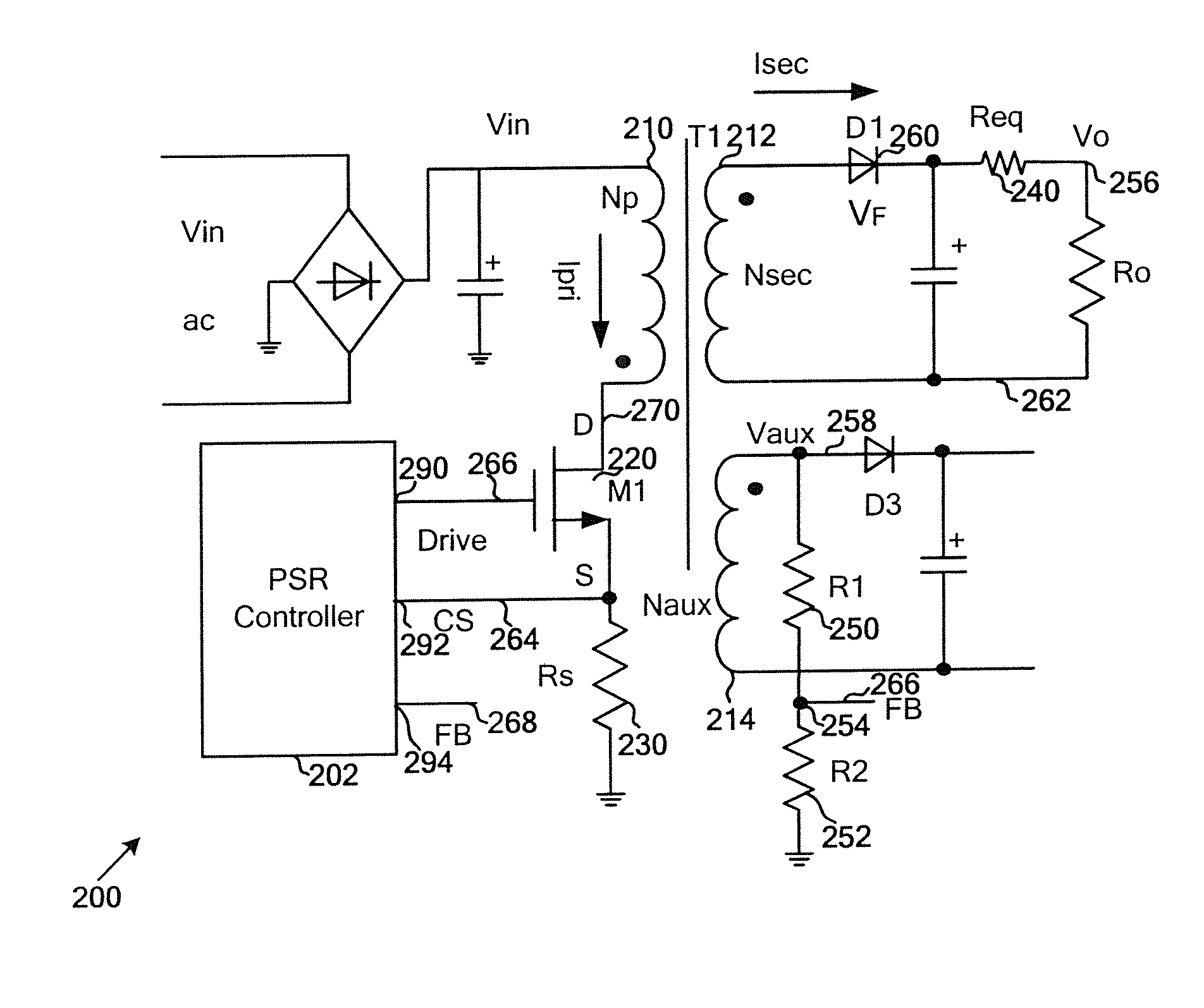
[0034]FIG. 2 is a simplified diagram showing a power conversion system according to an embodiment of the present invention. This diagram is merely an example, which should not unduly limit the scope of the claims. One of ordinary skill in the art would recognize many variations, alternatives, and modifications. The power conversion system 200 includes a controller 202, a primary winding 210, a secondary winding 212, an auxiliary winding 214, a power switch 220, a current sensing resistor 230, an equivalent resistor 240 for an output cable, resistors 250 and 252, and a rectifying diode 260. In addition, the controller 202 inc...


PUM


Abstract

Systems and methods are provided for regulating a power conversion system. An example system controller includes a driving component and a detection component. The driving component is configured to output a driving signal to a switch associated with a first current flowing through a primary winding of a power conversion system, the switch including a first switch terminal related to a first voltage and a second switch terminal related to a second voltage, the driving signal being associated with a plurality of switching periods. The detection component is configured to receive an input signal associated with a difference between the first voltage and the second voltage, detect at least one valley of the input signal in magnitude during a detection period for the first switching period, and output a detection signal based on at least information associated with the input signal to affect the driving signal.

Description


Claims


Application Information

Patent Timeline
Owner ON BRIGHT ELECTRONICS SHANGHAI
Learn More