Passively deployable air dam for a vehicle

a vehicle and air dam technology, applied in the field of air dams, can solve the problems of high motor cost, increased warranty cost, and too expensive active air dams for some models of automotive vehicles, so as to reduce the deployment cycle of air dams, improve high speed fuel economy, and reduce the effect of cost and warranty concerns

Active Publication Date: 2012-05-29
GM GLOBAL TECH OPERATIONS LLC
View PDF13 Cites 31 Cited by
  • Summary
  • Abstract
  • Description
  • Claims
  • Application Information

AI Technical Summary

Benefits of technology

[0007]An advantage of an embodiment is that a passively deployable air dam assembly improves high speed fuel economy without compromising concerns with low speed parking of the vehicle, while also eliminating concerns associated with motors, linkages and controllers that are employed with actively deployed air dams. The deployment of the air dam happens passively using aerodynamic pressures that occur naturally during vehicle operation, yet the deployment of the air dam can be controlled so that it retracts at a lower speed than it deploys, thus reducing the deployment cycling of the air dam. The benefits of an actively deployed air dam are achieved while avoiding the complications of a motor, linkages and a controller, thus reducing costs and warranty concerns. No power supply is needed for actuation.

Problems solved by technology

However, the high cost of the motor, linkages and controller make active air dams too expensive to use on some models of automotive vehicles.
Moreover, a potential for warranty cost increases exists due to the fact that a motor, linkage and wiring is packaged low and at the front of the vehicle, potentially exposing it to damage from the environment around the vehicle.
These active air dam systems may also add more weight to the vehicle than is desirable.

Method used


Image

  • Passively deployable air dam for a vehicle
  • Passively deployable air dam for a vehicle
  • Passively deployable air dam for a vehicle

Examples


Embodiment Construction

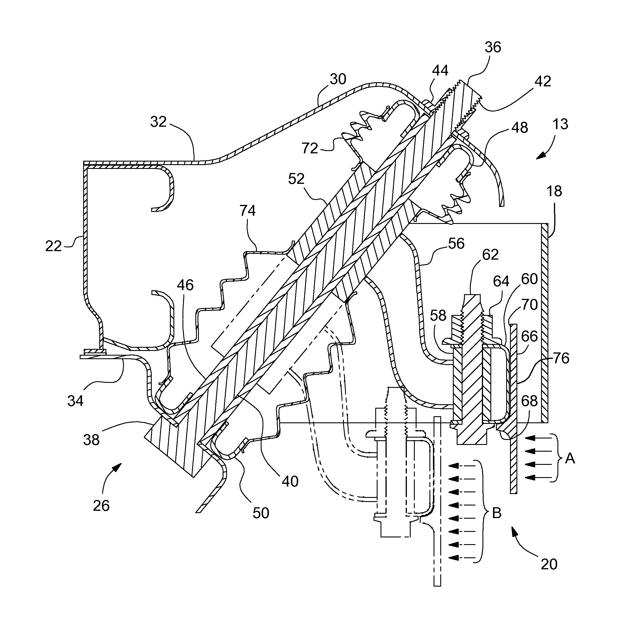
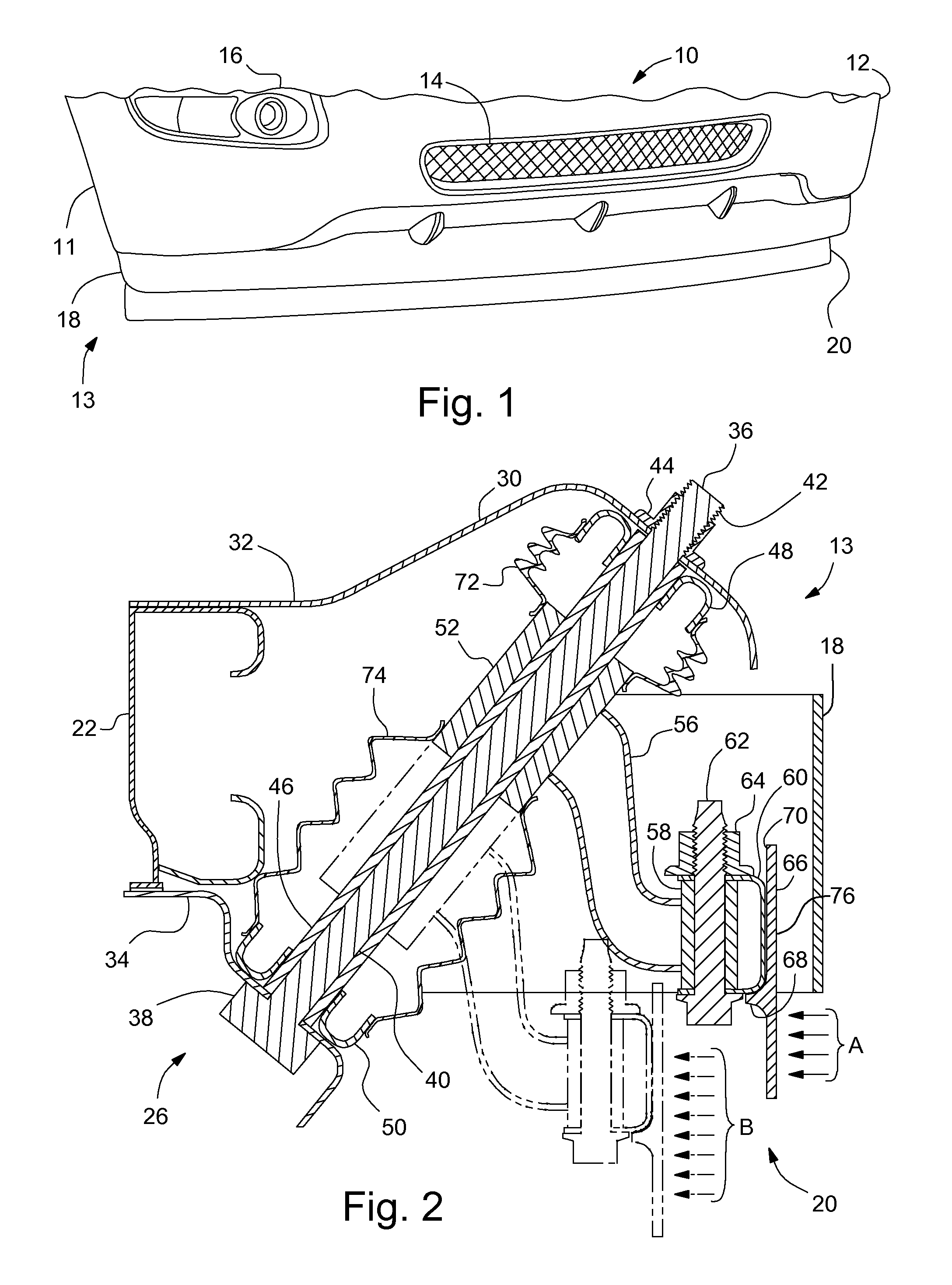
[0015]Referring to FIG. 1, a vehicle, indicated generally at 10, is shown. The vehicle 10 includes a front end 11 having a front fascia 12, a grille 14 and headlights 16. Below the fascia 12 is an air dam assembly 13 having a fixed air dam 18, which is not movable relative to the vehicle 10 during vehicle operation. The fixed air dam 18 may be supported by the front fascia 12 or any other suitable vehicle structure near the front end of the vehicle 10. The air dam assembly 13 also includes a passively deployable air dam assembly 20 mounted below and behind the fixed air dam 18. The passively deployable air dam assembly 20 can move relative to the vehicle 10 during vehicle operation.

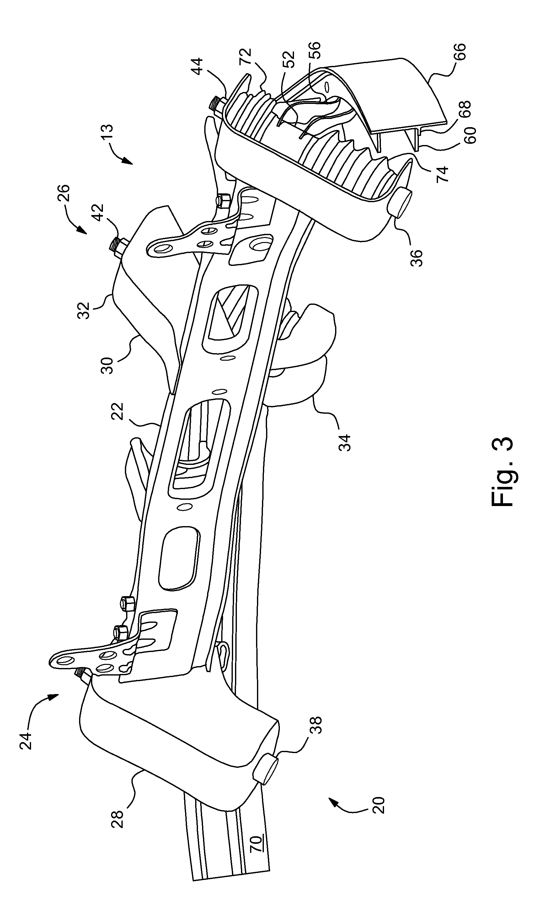
[0016]FIGS. 2-4 show various portions of the air dam assembly 13 and portions of the vehicle structure adjacent to the assembly 13. The deployable air dam assembly 20 is supported by vehicle structure near the front of the vehicle—in this embodiment, the support structure is a condenser, radiator and fan ...


PUM


Abstract

An air dam assembly mounted under a front end of a vehicle includes a passively deployable air dam assembly. The passively deployable air dam assembly includes a passively deployable air dam having a front surface at least partially exposed to ram air when the vehicle is traveling in a forward direction, and a passive deployment assembly including at least one spring biasing the passively deployable air dam into a retracted position, with the passive deployment assembly engaging the passively deployable air dam to allow the passively deployable air dam to move, against the bias of the spring, from the retracted position to a deployed position closer to ground under the vehicle when a forward speed of the vehicle reaches or exceeds a predetermined activation speed.

Description

BACKGROUND OF INVENTION[0001]The present invention relates generally to air dams for use below the front ends of automotive vehicles.[0002]In order to improve fuel economy at high speeds, some automotive vehicles employ air dams mounted below the front end of the vehicle. The lower ground clearance at the front end created by the air dam improves the aerodynamic drag on the vehicle at high speeds, thus improving fuel economy. These air dams are typically fixed in position. The tradeoff for the positioning of the air dam above the ground (i.e., ground clearance) is between a low height, the lower they are to the ground the better the aerodynamic drag at high speed, and a higher height off the ground, which protects the air dam from being damaged by contact with a curb or parking lot block when parking the vehicle.[0003]To overcome this tradeoff, some have replaced the fixed air dam with a moveable, active air dam that is automatically moved up and down via a motor and linkages contro...

Claims


Application Information

Patent Timeline
Patent Type & Authority Patents(United States)
IPC IPC(8): B60J1/20B62D35/02
CPCB60R19/40B62D35/005Y02T10/82
Inventor MACKENZIE, STEVEN K.LUTTINEN, JAMES L.CHARNESKY, SCOTT P.
Owner GM GLOBAL TECH OPERATIONS LLC
Why Eureka
Try Eureka