Method for performing continuous deployment and feedback from a radio network node

a radio network and node technology, applied in the direction of transmission, electrical equipment, connection management, etc., can solve the problems of time-consuming, difficult, costly, manual intervention, etc., and achieve the effect of reducing the deployment cycle, reducing labor and workforce costs, and increasing visibility

Active Publication Date: 2021-03-11
TELEFON AB LM ERICSSON (PUBL)
View PDF0 Cites 0 Cited by
  • Summary
  • Abstract
  • Description
  • Claims
  • Application Information

AI Technical Summary

Benefits of technology

[0016]The embodiments thereby enable a drastically reduced deployment cycle in comparison to deployment over the O&M network by removing obstacles to automation of the deployment activity.
[0017]The embodiments herein further have the benefit that they allow near real time feedback to be received from nodes by the CD Server. This allows the vendor of the network node to have greater visibility and required data for diagnostic and performance evaluation.
[0018]Furthermore, labor and workforce cost is reduced thereby contributing to a lower operational and maintenance cost of the network nodes.

Problems solved by technology

Configuring the O&M network to allow external access, such as from the vendor's side, with decent bandwidth in order to continuously transfer node specific data, such as diagnostics, new software, performance data etc., is time consuming, difficult, costly and in many cases requires manual intervention.
Therefore, this process is difficult to generalize as it depends on the policies and the network configurations of the individual operator.
This makes it rather difficult to have an automated CD process using the O&M architecture.
The architecture is not meant to facilitate continuous deployment focusing on automating and high deployment frequency.

Method used


Image

  • Method for performing continuous deployment and feedback from a radio network node
  • Method for performing continuous deployment and feedback from a radio network node
  • Method for performing continuous deployment and feedback from a radio network node

Examples


Embodiment Construction

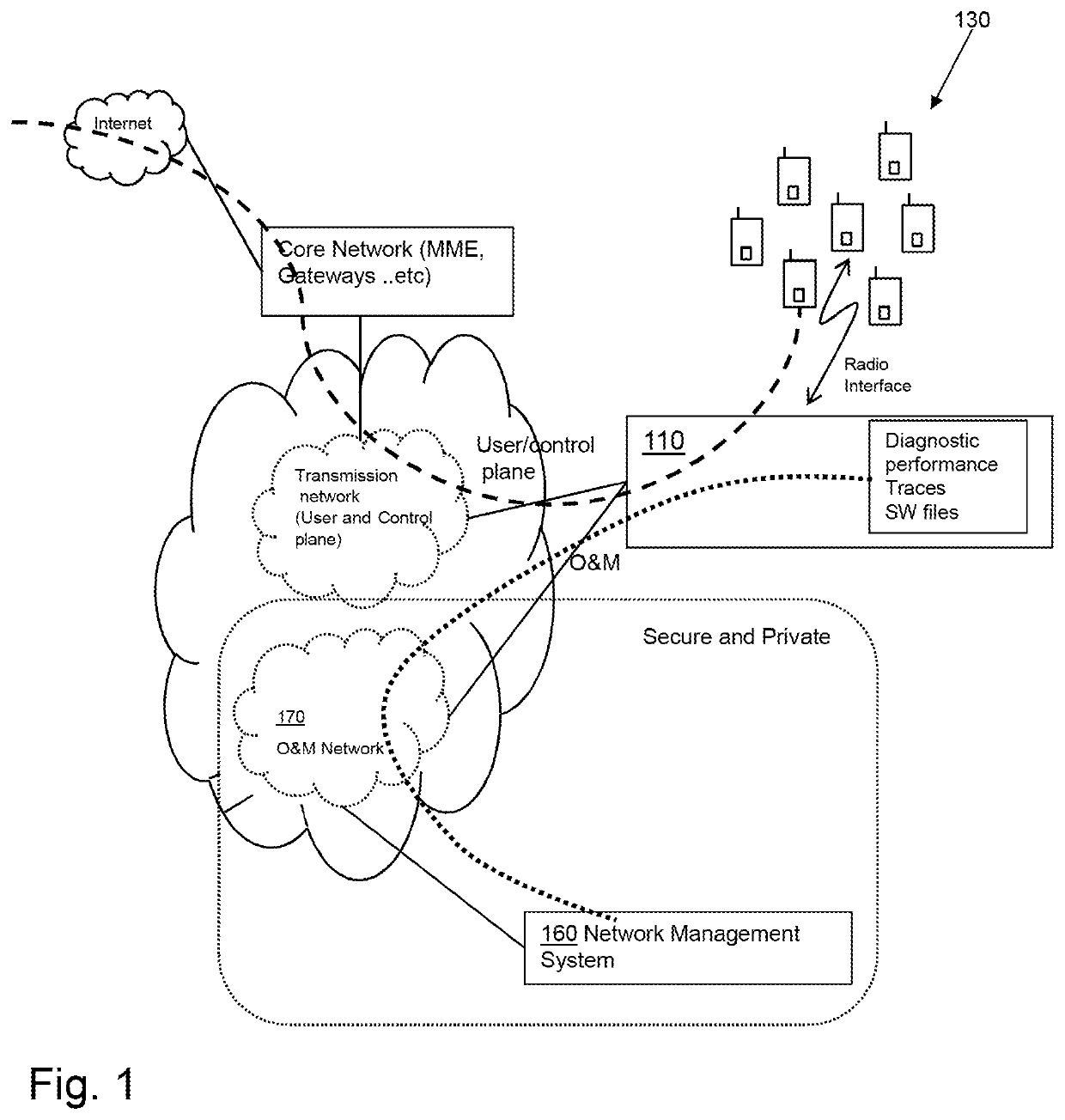
[0028]FIG. 1 discloses an example of a known communication network, which allows the transport network to separate between O&M traffic and user plane / control plane. The radio network node 110 is connected to a Network Management System (NMS) 160 via an O&M network 170 and may exchange information with the NMS 160 via a physical interface which may also be used as the user / control plane interface. The same interface may further be used by one or more mobile terminals 130, such as a UE, for user and control plane traffic. The O&M network 170 is a secure and private network which may be only accessed by obtaining several levels of security credentials from the outside. Establishing a connection to the radio network node 110 typically first requires access to a Management System, by which a session may be established to an O&M address of the radio network node 110. Therefore, uploading new software into the radio network node 110, or sending diagnostic and performance data to the vendor...


PUM


Abstract

Embodiments herein relate to a method for performing continuous deployment and feedback between a radio network node and a Continuous Deployment server. The radio network node is configured to mimic a behavior of a mobile terminal towards a core network. The radio network node sends a message comprising a request to establish an end-to-end connection with the CD server to a core network node. The message further comprises a mobile identity identifying the radio network node as a mobile terminal. The radio network node receives an access bearer establishing a user plane connection between radio network node and the core network node over a user plane interface, from the core network node. The radio network node establishes a communication channel between the radio network node and the CD server over the user plane interface and an external packet switched network. The radio network node exchanges information between the radio network node and the CD server over the established communication channel. Embodiments herein further relate to a method performed by a CD server, a radio network node and a CD server.

Description

TECHNICAL FIELD[0001]Embodiments herein relate to a method and a radio network node for performing continuous deployment and diagnostic and operations feedback in a telecommunications network.BACKGROUND OF THE INVENTION[0002]Continuous Deployment (CD) is changing the software industry. It started with online and web applications and now taking over in embedded systems products such as automobiles industries. One aim of CD is to minimize lead time, the time elapsed between development writing one new line of code and this new code being used by live users, in production. CD relies on infrastructure that automates deployment and feedback process in quick and efficient manner.[0003]CD allows the organization developing a software, such as e.g. a vendor of a radio network node, to deploy newly developed software code as frequently and quickly as possible to production live systems, such as e.g. radio network nodes in commercial customer networks. Each deployment gives the development or...

Claims


Application Information

Patent Timeline
Patent Type & Authority Applications(United States)
IPC IPC(8): H04W76/10H04W4/50
CPCH04W76/10H04W4/50H04L41/04H04L41/082H04L67/34G06F8/65G06F9/445H04L41/34
Inventor DAKKAK, ANASSKÄRBY, CHRISTIANSTÅHL, DANIEL
Owner TELEFON AB LM ERICSSON (PUBL)
Why Eureka
Try Eureka