Systems and Methods for Output Current Regulation in Power Conversion Systems

Active Publication Date: 2016-11-17
ON BRIGHT ELECTRONICS SHANGHAI
View PDF0 Cites 29 Cited by
  • Summary
  • Abstract
  • Description
  • Claims
  • Application Information

AI Technical Summary

Benefits of technology

[0021]Depending upon embodiment, one or more benefits may be achieved. These benefits and various additional objects, features and advan

Problems solved by technology

But the system 100 often can

Method used


Image

  • Systems and Methods for Output Current Regulation in Power Conversion Systems
  • Systems and Methods for Output Current Regulation in Power Conversion Systems
  • Systems and Methods for Output Current Regulation in Power Conversion Systems

Examples


Embodiment Construction

[0034]Certain embodiments of the present invention are directed to integrated circuits. More particularly, some embodiments of the invention provide systems and methods for regulating output currents. Merely by way of example, some embodiments of the invention have been applied to power conversion systems. But it would be recognized that the invention has a much broader range of applicability.

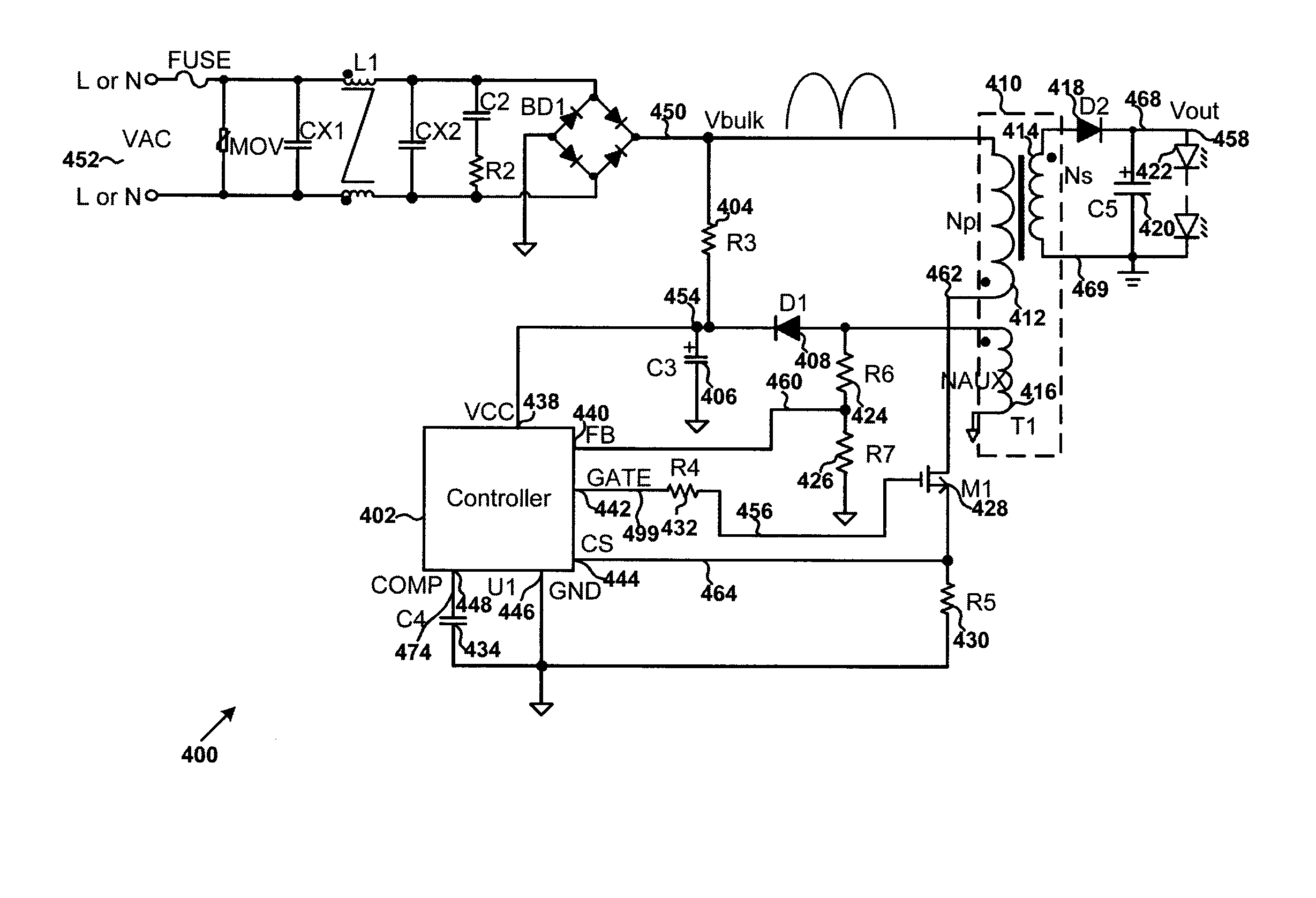
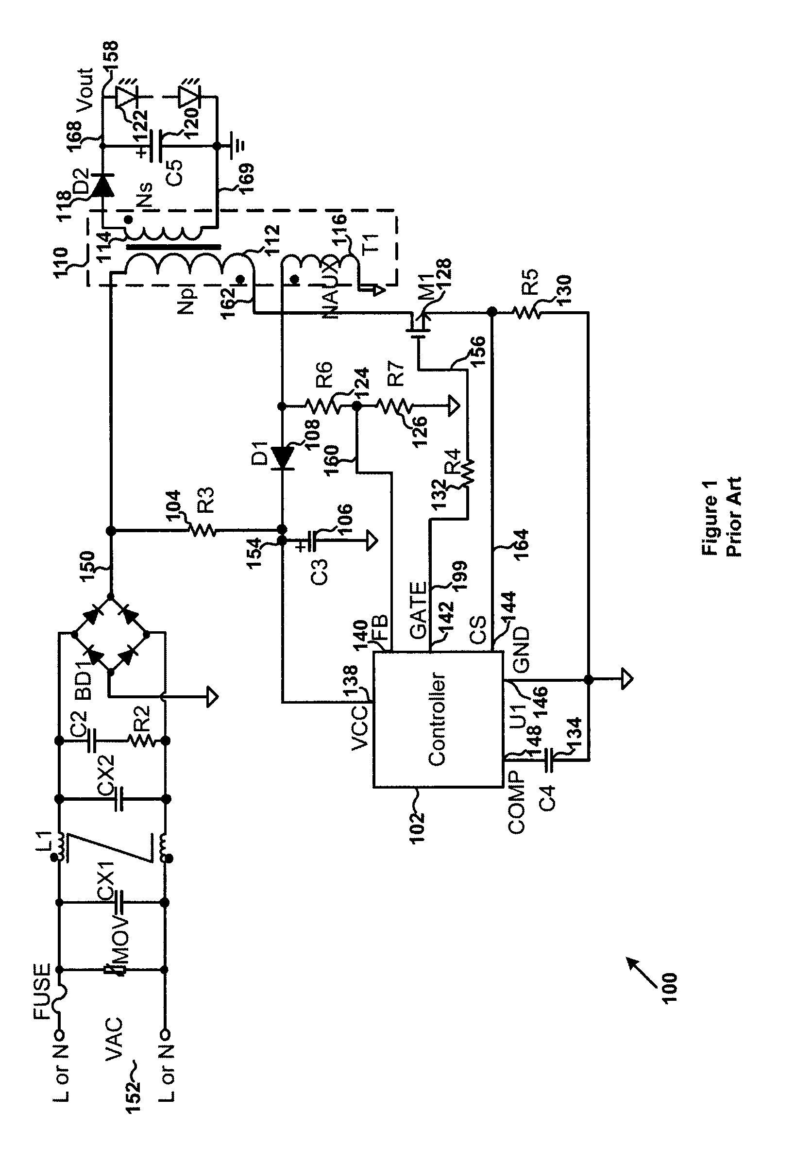
[0035]Referring to FIG. 1, to achieve high efficiency (e.g., >90%), the system 100 may operate in a quasi-resonant (QR) mode, as an example. A peak value of the primary current 162 is determined as follows:

Iin_peak=(TonLp)·Vbulk(Equation2)

where Iin_peak represents a peak value of the primary current 162, Ton represents an on-time period during which the power switch 128 is closed (e.g., being turned on), Vbulk represents the bulk voltage 150, and Lp represents the inductance of the primary winding 112.

[0036]For example, assuming the on-time period associated with the power switch 128 keeps appr...


PUM


Abstract

Systems and methods are provided for regulating power conversion systems. A system controller includes: a first controller terminal configured to receive a first signal related to an input signal for a primary winding of a power conversation system; and a second controller terminal configured to output a drive signal to a switch to affect a current flowing through the primary winding, the drive signal being associated with a switching period including an on-time period and an off-time period. The switch is closed (e.g., being turned on) in response to the drive signal during the on-time period. The switch is opened (e.g., being turned off) in response to the drive signal during the off-time period. A duty cycle is equal to a duration of the on-time period divided by a duration of the switching period. The system controller is configured to keep a multiplication product of the duty cycle and the duration of the on-time period approximately constant.

Description

1. CROSS-REFERENCES TO RELATED APPLICATIONS[0001]This application claims priority to Chinese Patent Application No. 201510249026.4, filed May 15, 2015, commonly assigned, incorporated by reference herein for all purposes.2. BACKGROUND OF THE INVENTION[0002]Certain embodiments of the present invention are directed to integrated circuits. More particularly, some embodiments of the invention provide systems and methods for regulating output currents. Merely by way of example, some embodiments of the invention have been applied to power conversion systems. But it would be recognized that the invention has a much broader range of applicability.[0003]Light emitting diodes (LEDs) are widely used for lighting applications. Oftentimes, approximately constant currents are used to control working currents of LEDs to achieve constant brightness. FIG. 1 is a simplified diagram showing a conventional LED lighting system. The LED lighting system 100 includes a system controller 102, resistors 104,...

Claims


Application Information

Patent Timeline
IPC IPC(8): H02M3/335H05B44/00
CPCH02M3/33515H02M3/156H05B45/37H02M1/12H02M3/33507H02M1/4258Y02B70/10Y02B20/40
Inventor FANG, QIANZHAI, XIANGKUNFANG, LIEYI
Owner ON BRIGHT ELECTRONICS SHANGHAI
Why Eureka
Try Eureka