Mooring device

a mooring device and mooring technology, applied in the direction of moorings, special-purpose vessels, vessel parts, etc., can solve the problems of affecting the aquatic environment, affecting the safety of passengers, etc., to achieve the effect of reducing the environmental impact on the aquatic environment, easy storage, transportation and installation, and reducing the environmental impa

Inactive Publication Date: 2015-03-05
GREENSTICK ENERGY
View PDF11 Cites 25 Cited by
  • Summary
  • Abstract
  • Description
  • Claims
  • Application Information

AI Technical Summary

Benefits of technology

[0007]Embodiments of the invention seek to provide an alternative and improved mooring device and method of mounting a mooring device. Embodiments of the present invention seek to minimise, overcome or avoid at least some of the problems and disadvantages associated with prior art mooring devices. Embodiments of the invention seek to provide a mooring device that has a minimal or limiting environmental effect on the aquatic environment. Embodiments of the invention seek to provide a mooring device that is more compact, lightweight

Problems solved by technology

It has been found that the installation, mounting and/or removal of the anchors and mooring lines can have a detrimental environmental impact on the aquatic environment.
For example, the anchors and/or mooring lines may damage the aquatic environment as they are dragged or moved along the floor supporting the body of water.
Although these types of anchors are able to provide a sufficient anchoring effect, they are bulky, heavy, expensive to manufacture, difficult to transport and install, are limited for use in only

Method used


Image

  • Mooring device
  • Mooring device
  • Mooring device

Examples


first embodiment

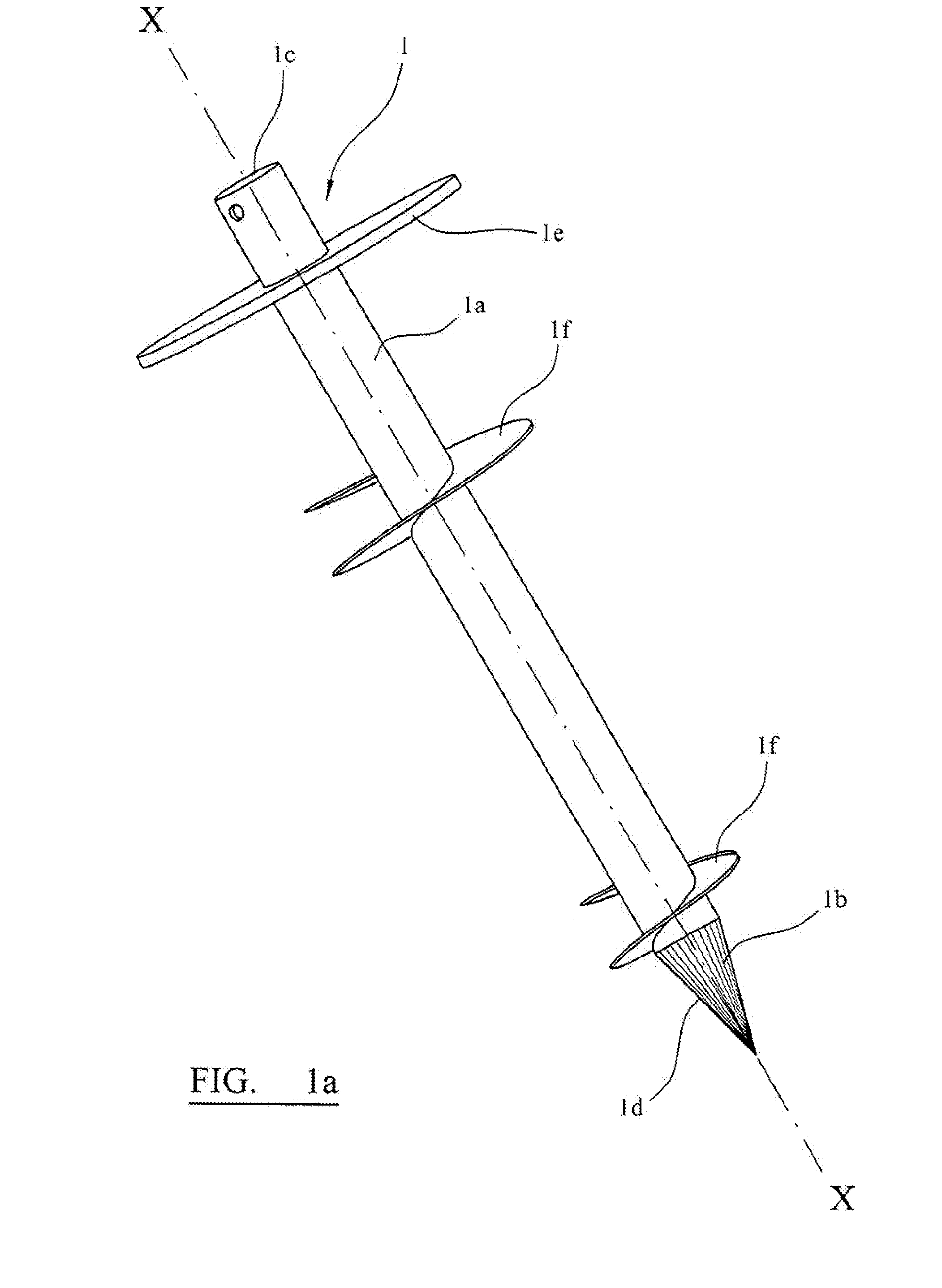
[0138]FIG. 1a depicts pile of the mooring device. The pile (1) comprises a shaft (1a) having a leading end (1b) and a trailing end (1c). The pile is formed from steel, it has a shaft length of approximately 2 m and a uniform shaft diameter of approximately 9 cm. A tip (1d) is formed at the leading end of the shaft. A stop plate (1e) is arranged approximately 1.5 m from the leading end of the shaft. Two helical plates (1f) with a maximum helix diameter of approximately 30 cm are mounted in spaced relation on the shaft between the tip and the stop plate. The longitudinal axis (XX) of the pile extends along the shaft from the leading end to the trailing end.

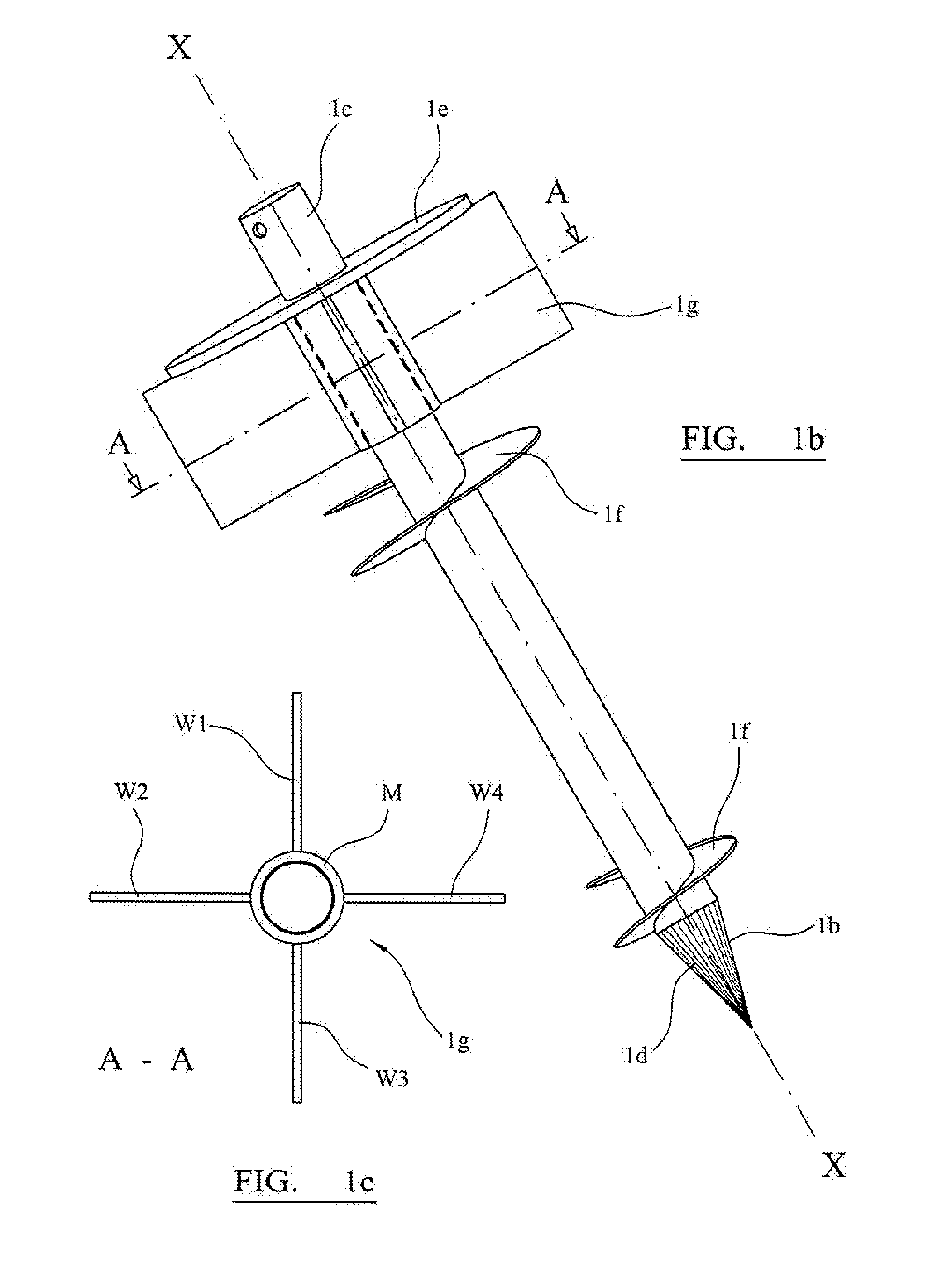
[0139]FIG. 1b depicts a pile of a second embodiment of the mooring device. As with the first embodiment, the pile comprises a shaft (1a) having a leading end (1b) and trailing end (1c). A tip (1d) is formed at the leading end of the shaft. A removable stop plate (1e) is arranged a predetermined distance from the leading end of the s...

second embodiment

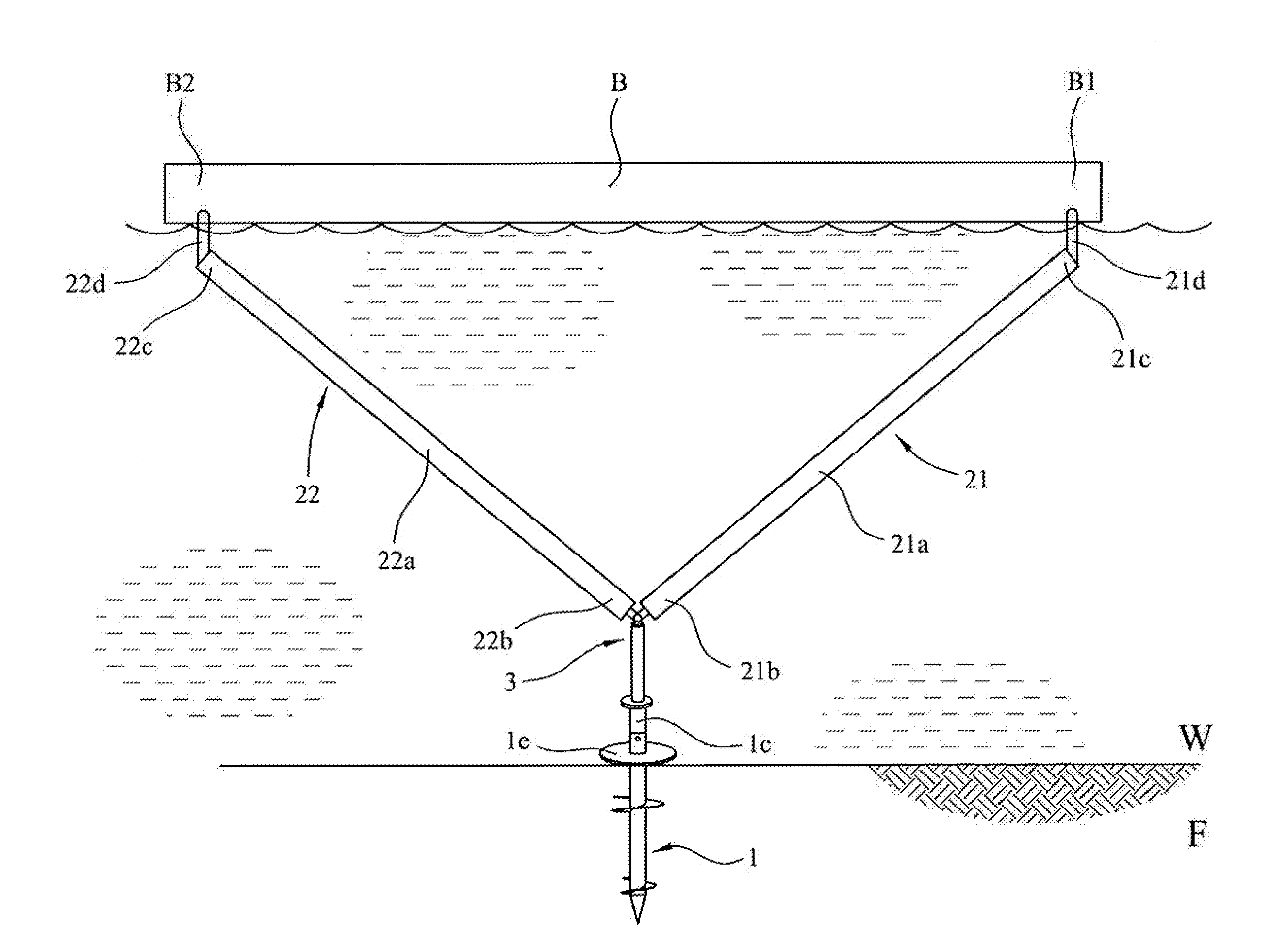
[0159]FIG. 2b depicts a mooring device mounted in a body of water (F). The mooring device comprises a pile (1) as depicted in FIG. 1, a first arm (21), a second arm (22), a joint (3) and joint locking means (not shown). The mooring device moors an elongate floatable body (B) that floats on the surface of the water and extends between the first arm and the second arm. The pile is vertically embedded into the floor (F) to a depth where the stop plate (1e) abuts the surface of the floor and the trailing end (1c) protrudes above the floor. The first arm and second arm have an identical configuration. The first arm comprises a shaft (21a) having a first end (21b) and a second end (21c) and also a catch (21d) arranged at the second end for coupling a first end (B1) of an elongate floatable body. Likewise, the second arm comprises a shaft (22a) having a first end (22b) and second end (22c) and a catch (22d) arranged at the second end to couple the second end (B2) of the floatable body. The...

third embodiment

[0178]FIG. 5 depicts an exploded view of a joint (3) comprising a swivel hinge joint (32) and a clevis hinge joint (33). The swivel hinge joint (32) comprises a shaft portion (32a) that is indirectly coupled to the arm (2) and a recess portion (32b) that is directly coupled the trailing end of the pile (1c) whereby the shaft portion is rotatably mounted in the recess portion to allow for rotation of the arm around the shaft axis. The clevis hinge joint (33) comprises a tang portion (33a) that is directly coupled to the first end of the arm (2a) and a fork portion (33b) that is indirectly coupled to the pile, whereby the tang portion is rotatably coupled to the fork portion by a clevis pin (33c) to allow for rotation of the arm around the clevis pin axis which is perpendicular to the longitudinal axis of the pile. Hence, if the pile is vertically embedded in the floor, the swivel hinge joint allows the arm to rotate with respect to the pile around a vertical axis (in a horizontal pla...


PUM


Abstract

The invention relates to a mooring device that is suitable for use in water. The mooring device includes a pile configured to be embedded in a floor supporting the body of water, at least one arm configured to engage at least one entity; a joint configured to couple the pile and the at least one arm and permit rotation of the at least one arm relative to the pile, and joint locking means configured to lock the joint. The invention may further relate to a method of mounting the mooring device in water, a mooring system including multiple mooring devices and a system including the mooring devices.

Description

FIELD OF ART[0001]The invention relates to mooring devices that are suitable for use in water. The water may be a moving body of water. The invention further relates to a method of mounting the mooring device in water and to systems that incorporate the mooring device.BACKGROUND TO THE INVENTION[0002]A mooring device is a structure for securing (retaining) an object in an aquatic environment.[0003]Mooring devices that are suitable for mounting in a body of water generally include one or more anchors and one or more mooring lines which extend from the anchor to an object.[0004]It has been found that the installation, mounting and / or removal of the anchors and mooring lines can have a detrimental environmental impact on the aquatic environment. For example, the anchors and / or mooring lines may damage the aquatic environment as they are dragged or moved along the floor supporting the body of water.[0005]Certain mooring devices use dead weight or mushroom anchors to permanently anchor t...

Claims


Application Information

Patent Timeline
IPC IPC(8): B63B21/00F16L1/16F03B13/22E02B8/00F03B13/18F03B13/26
CPCB63B21/00F03B13/1805F03B13/262F03B13/22E02B8/00F16L1/16B63B2021/003B63B21/26E02B3/24F03B13/1815F03B13/264F05B2240/97Y02E10/30E02B3/06E02B17/00F03B13/186F03B13/187F03B13/1875F16L1/12F03B13/26B63B21/507B63B39/10B63B2039/105Y02E10/20
Inventor MELTSOV, GENNADYWEST, DAVID
Owner GREENSTICK ENERGY
Why Eureka
Try Eureka