Multi-stage transmission

a transmission and multi-stage technology, applied in the direction of gearing details, gearing, transportation and packaging, etc., can solve the problems of nesting of particular parts and the complex coupling of the two gear sets in comparison, so as to reduce mechanical and/or hydraulic losses, less energy, and pressure loss also low

Inactive Publication Date: 2015-03-05
ZF FRIEDRICHSHAFEN AG
View PDF6 Cites 4 Cited by
  • Summary
  • Abstract
  • Description
  • Claims
  • Application Information

AI Technical Summary

Benefits of technology

[0016]Through the selected configuration, it can be achieved that the shift elements, meaning the brakes and clutches at the transmission side, are well accessible from the outside. Thus, actuators such as for instance electric motors, hydraulic valves, hydraulic pumps or similar can be positioned near the shift elements which reduces mechanical and / or hydraulic losses, and less energy might be needed for the actuation of the shift elements. Also, less energy might be needed to keep the shift element in each of its actual operating modes, meaning disengaged or engaged, where, for instance, the pressure losses are also lower through shorter pipes. It is also possible to position the shift elements on the housing and thus at least partially rotationally fixed, whereby gaskets which connect a fixed pipe with a rotating pipe, can be completely or partially omitted.
[0017]Also, the spatial positioning of the well accessible shift elements simplifies the replacement of the traditional, hydraulically actuated disc clutches or disc brakes with, for instance, electro-mechanically or electro-hydraulically actuated brakes and clutches, which in comparison can be actuated very simply. Easily accessible shift elements are, on one hand, brakes, which connect a shaft with the housing in a rotationally fixed manner, but also shift elements and outer positioned shafts of the multistep transmission, preferably at a drive shaft or output shaft, where in comparison the needed hydraulic fluid for the activation can easily be supplied.
[0018]Beside this characteristic, the named multistep transmission also has at the same time good gear efficiency, low stress on parts, in particular low planetary set and shift element torques, low absolute and relative rotational speeds, as well as a lower need for construction space. The latter enables the multistep transmission to be realized with lower weight and lower cost. In particular, the length of the proposed transmission is extremely short. Therefore, the multistep transmission is preferably constructed as a drive with a front-transverse configuration. In particular, the transmission can also be utilized, due to its short length, in hybrid drives (for instance combustion engines and electric machines). Finally, the multistep transmission also enables a good gear ratio sequence, meaning a well applicable gradation of the gear steps.

Problems solved by technology

A disadvantage in this known multi step transmission is the nesting of the particular parts, especially the coupling of the two gear sets is in comparison rather complex.

Method used


Image

  • Multi-stage transmission
  • Multi-stage transmission
  • Multi-stage transmission

Examples


Embodiment Construction

[0025]By way of introduction it should be noted that in the different embodiments described like parts have like reference numbers or same component names, the disclosure contained in the description can be usefully applied to the same parts with the same reference numbers or same component names. Also, the wording of positions which has been used in the description, such as for instance top, bottom, side etc., refers to the specific and presented drawings and can be applied accordingly to new positions in the case of a change of the position. In addition, also individual features or combinations of features of the presented and described drawings of the different embodiments can represent by themselves either inventive or the invention related solutions.

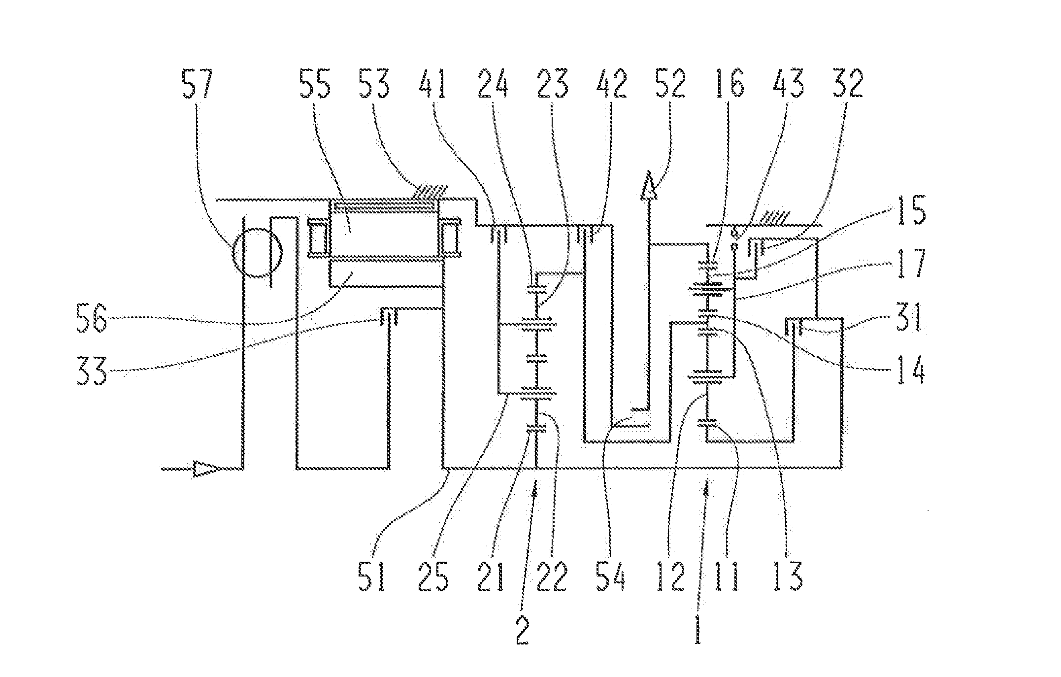
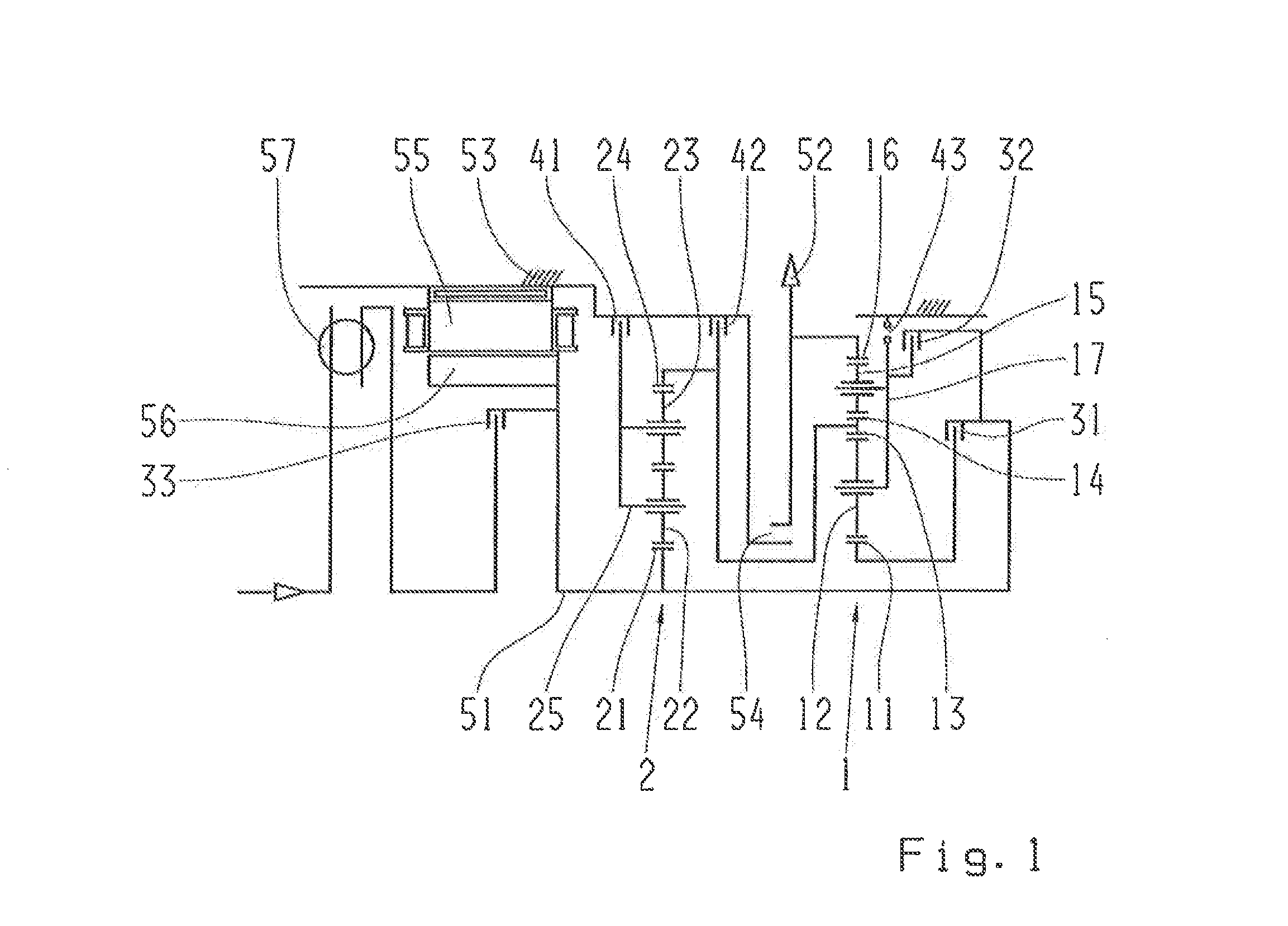
[0026]FIG. 1 shows a first schematically presented variation of a multistep transmission in accordance with the invention and with two planetary gear sets.

[0027]The first planetary gear set is comprised of an inner sun gear 11, inne...


PUM


Abstract

A two-step multi-step transmission in which a first planetary gear set (1) has two radially nested transmission sub-assemblies. The first planetary gearset has an inner sun gear (11), inner planetary gears (12), an outer sun gear (14) which is rotationally fixed to the inner ring gear (13), outer planetary gears (15), an outer ring gear (16), and a carrier (17) on which the inner planetary gears (12) and the outer planetary gears (15) are mounted. The inner ring gear (13) and the outer sun gear (14), respectively, are rotationally fixed to a second, traditionally designed planetary gear set (2) and can be locked via a brake (42).

Description

[0001]This application is a National Stage completion of PCT / EP2013 / 055056 filed Mar. 13, 2013, which claims priority from a German patent application serial no. 10 2012 207 017.6 filed Apr. 27, 2012.FIELD OF THE INVENTION[0002]The invention concerns a multi-stage transmission in a planetary construction, in particular for a motor vehicle, comprising:[0003]a first planetary gear set having an inner sun gear, planetary gears which mesh with the inner sun gear, an inner ring gear which meshes with the inner planetary gears, an outer sun gear which is connected in a rotationally fixed manner with the inner ring gear, outer planetary gears which mesh with the outer sun gear, an outer ring gear which meshes with the outer planetary gears, and a carrier on which the inner planetary gears and outer planetary gears are mounted, and[0004]a second planetary gear set with a sun gear, inner planetary gears which mesh with the sun gear, outer planetary gears which mesh with the inner planetary g...

Claims


Application Information

Patent Timeline
Patent Type & Authority Applications(United States)
IPC IPC(8): F16H3/44
CPCF16H3/44B60K2006/4825F16H2200/2094F16H2003/442F16H2200/0008F16H2200/201F16H2200/0052F16H2200/2043F16H3/666Y02T10/62B60K6/365B60K6/48B60K6/547
Inventor ZIEMER, PETERBECK, STEFANWEHLEN, TIMO
Owner ZF FRIEDRICHSHAFEN AG
Why Eureka
Try Eureka