Tensioning device for a traction-device drive

Inactive Publication Date: 2014-03-27
SCHAEFFLER TECH AG & CO KG
View PDF42 Cites 0 Cited by
  • Summary
  • Abstract
  • Description
  • Claims
  • Application Information

AI Technical Summary

Benefits of technology

The present invention provides an improved tensioning device for a traction-device drive that can actively reduce resonant vibrations of the traction device in an optimal way over the entire operating speed range. The device takes into account the basic goal of optimized energy utilization. The tensioning elements can be controlled as a function of instantaneous vibrations of the traction device, which makes it possible to quickly reduce unwanted vibrations and resulting undesired effects upon occurrence. The device also integrates an energy storage device to store the voltage induced in the magnetic circuit of the electromagnetic actuator due to the deflections of the traction device, without the need for a separate power supply. This reduces the mechanical and thermal stresses on the bearing systems and increases the service life of them. In summary, the invention optimizes the performance and durability of the traction-device drive.

Problems solved by technology

While tensioning devices can be optimally adjusted to such a resonance zone, often only a compromise solution is obtained for ranges outside the resonance zone with respect to the adjustment of the tensioning device.

Method used


Image

  • Tensioning device for a traction-device drive
  • Tensioning device for a traction-device drive

Examples


first embodiment

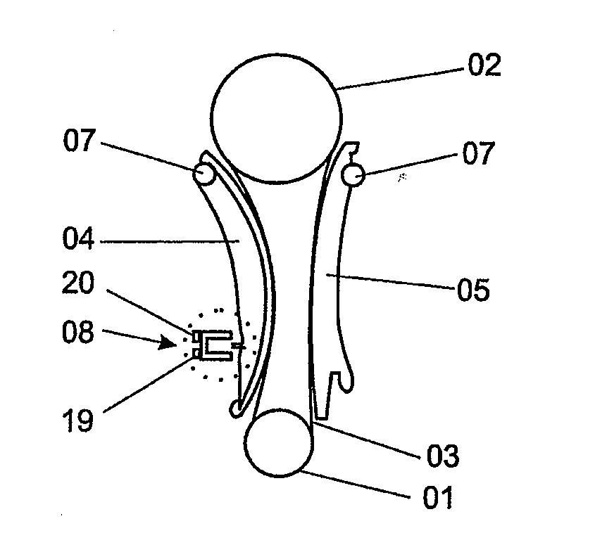
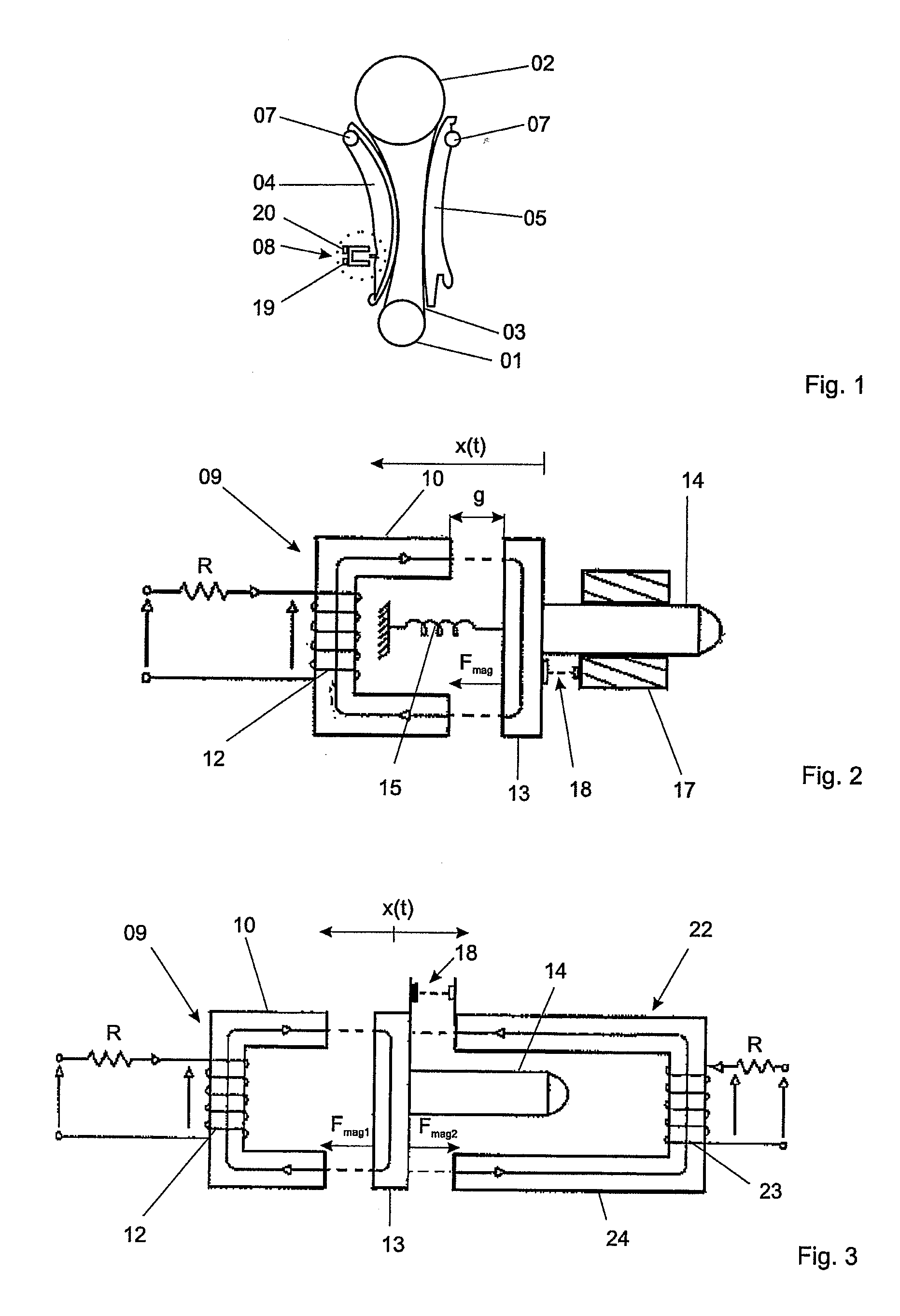
[0019]FIG. 2 shows the tensioning device according to the present invention. The inventive tensioning device 08 includes an electromagnetic actuator 09 including a first electromagnet 10 having a first coil 12 for generating a magnetic flux, and further including a displaceable armature 13. Armature 13 is connected to a pusher 14. When first electromagnet 10 is energized, pusher 14 is movable against the force of a pre-tensioning element 15. In the embodiment shown, the pre-tensioning element takes the form of a spring element 15. The end of pusher 14 is in contact with tensioning blade 04 to cause the desired tensioning force to act on the traction device 03. The force provided by energizing first electromagnet 10 acts via displaceable armature 13 and the pusher 14 connected thereto in a direction transverse to the longitudinal extent of the traction device 03 to be tensioned. The force introduced by pusher 14 is approximately normal to the running surface of traction device 03 in ...

second embodiment

[0031]FIG. 3 shows the tensioning device according to the present invention. This embodiment differs from that shown in FIG. 2 in that the pre-tensioning element is implemented using a magnetic circuit 22 instead of a spring element 15. Thus, two magnetic circuits are present in this embodiment. The first magnetic circuit includes first electromagnet 10 with first coil 12, and armature 13. The side of armature 13 facing away from the end of pusher 14 that acts on tensioning blade 04 faces the first electromagnet 10. Second magnetic circuit 22 is formed by a second electromagnet 23 having a second coil 24 for generating a magnetic flux, and armature 13. The side of armature 13 facing the end of pusher 14 that acts on tensioning blade 04 faces the second electromagnet 23. Pusher 14 may extend at least partially between the legs of the second electromagnet. The leg ends of second electromagnet 23 are preferably oriented parallel to pusher 14. The region of the leg ends oriented paralle...


PUM


Abstract

A tensioning device (08) for a traction-device drive having a dynamically operable tensioning element (04) which acts on a traction device (03). It is a feature of the tensioning device that it has an electromagnetic actuator (09) for operating the tensioning element (04) as a function of deflections of the traction device (03) transverse to the longitudinal extent of the traction device (03).

Description

[0001]This claims the benefit of German Patent Application DE 10 2012 217 206.8, filed Sep. 24, 2012 and hereby incorporated by reference herein.[0002]The present invention relates to a tensioning device for a traction-device drive having a dynamically operable tensioning element which acts on a traction device.BACKGROUND[0003]Traction-device drives are used, inter alia, to transmit rotational movements in internal combustion engines. For example, the rotation of a crankshaft can be transmitted to camshafts by a traction device. The traction device used in traction-device drives include straps, belts, V-belts, toothed belts, or chains. Transmission of force takes place over a large speed range, for example, up to the maximum speed of the internal combustion engine. In order to maintain the traction device under sufficient pretension so as to keep it from coming off a driving wheel and to prevent tooth jumping and excessive slippage, it is known to use a tensioning device which has a...

Claims


Application Information

Patent Timeline
IPC IPC(8): F16H7/08
CPCF16H7/0829
Inventor ARIMA, GILSONPINTO, MARCOS BERNARDCARNEIRO, BRENOJUNGHAHNEL, MARIO
Owner SCHAEFFLER TECH AG & CO KG
Why Eureka
Try Eureka