Method for the correction of the reduced mass flow rate of a compressor in an internal combustion engine turbocharged by means of a turbocharger

a compressor and internal combustion engine technology, which is applied in the direction of combustion engines, machines/engines, electric control, etc., can solve the problems of certain time drift, high structure dispersion of the spring of the pneumatic actuator, and considerable thermal dri

Active Publication Date: 2015-03-12
MARELLI EURO SPA
View PDF2 Cites 9 Cited by
  • Summary
  • Abstract
  • Description
  • Claims
  • Application Information

AI Technical Summary

Benefits of technology

[0013]The object of the present invention is to provide a method for correcting the reduced mass flow rate of a compressor in an internal combustion engine turbocharged by means of a turbocharger, this correction method being devoid of the above-described drawbacks and, in particular, simple and inexpensive to implement.

Problems solved by technology

However, the preload generated by the contrast spring of the pneumatic actuator has high structure dispersion, considerable thermal drift and also a certain time drift.
Furthermore, the pneumatic actuator has considerable hysteresis, i.e. the behaviour of the pneumatic actuator varies significantly between the opening movement and the opposite closing movement.
In consequence, the control map used to determine the closed-loop contribution is highly nonlinear and pursuing the objective supercharging pressure proves to be complicated; thus, pursuing the objective supercharging pressure in known internal combustion engines tends to have large overshoots or undershoots (i.e. the actual supercharging pressure significantly exceeds or drops below the objective supercharging pressure) and thus causes oscillations, especially when the supercharging pressure is around the operating threshold, below which the wastegate may not be opened by the action exerted by the solenoid control valve.
Overshoots (i.e. peaks) in the supercharging pressure are particularly troublesome because they cause significant stress (and therefore potential damage over time) to the mechanical components of the internal combustion engine and because they generate both noise perceptible by the vehicle occupants and corresponding undesired oscillations in the drive torque generated by the internal combustion engine.

Method used


Image

  • Method for the correction of the reduced mass flow rate of a compressor in an internal combustion engine turbocharged by means of a turbocharger
  • Method for the correction of the reduced mass flow rate of a compressor in an internal combustion engine turbocharged by means of a turbocharger
  • Method for the correction of the reduced mass flow rate of a compressor in an internal combustion engine turbocharged by means of a turbocharger

Examples


Embodiment Construction

[0013]The object of the present invention is to provide a method for correcting the reduced mass flow rate of a compressor in an internal combustion engine turbocharged by means of a turbocharger, this correction method being devoid of the above-described drawbacks and, in particular, simple and inexpensive to implement.

[0014]According to the present invention, a method for correcting the reduced mass flow rate of a compressor in an internal combustion engine turbocharged by means of a turbocharger is provided as claimed in the appended claims.

BRIEF DESCRIPTION OF DRAWINGS

[0015]The present invention will now be described with reference to the accompanying drawings, which illustrate a non-limitative embodiment thereof, in which:

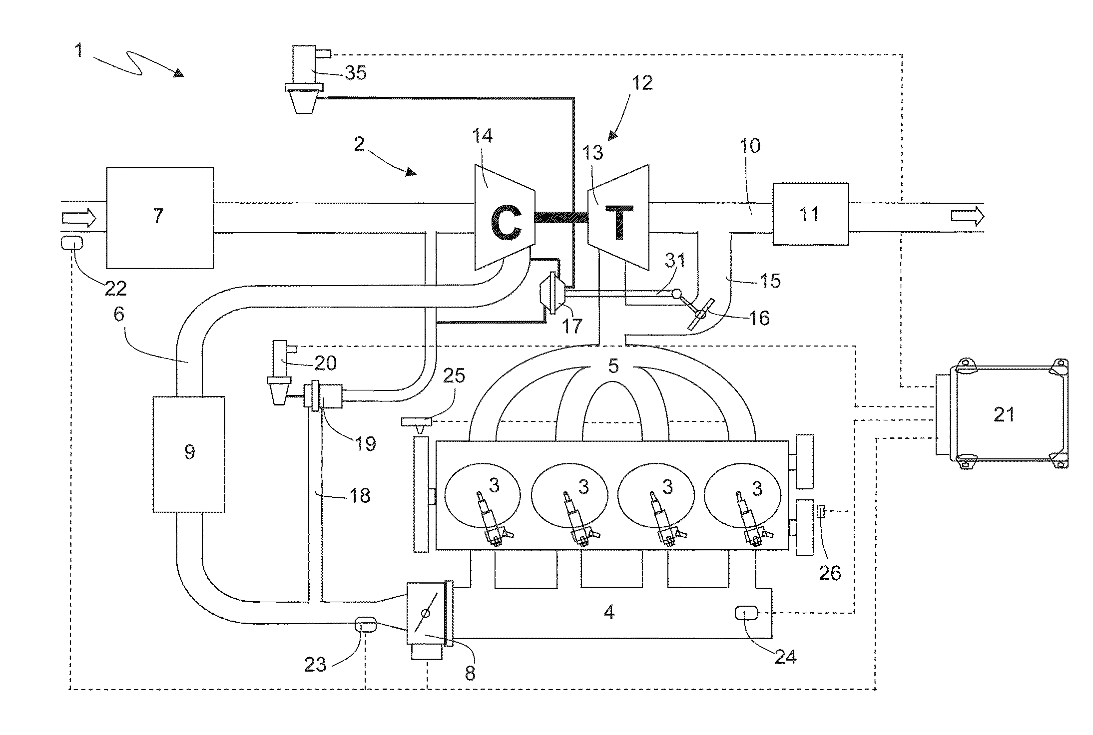
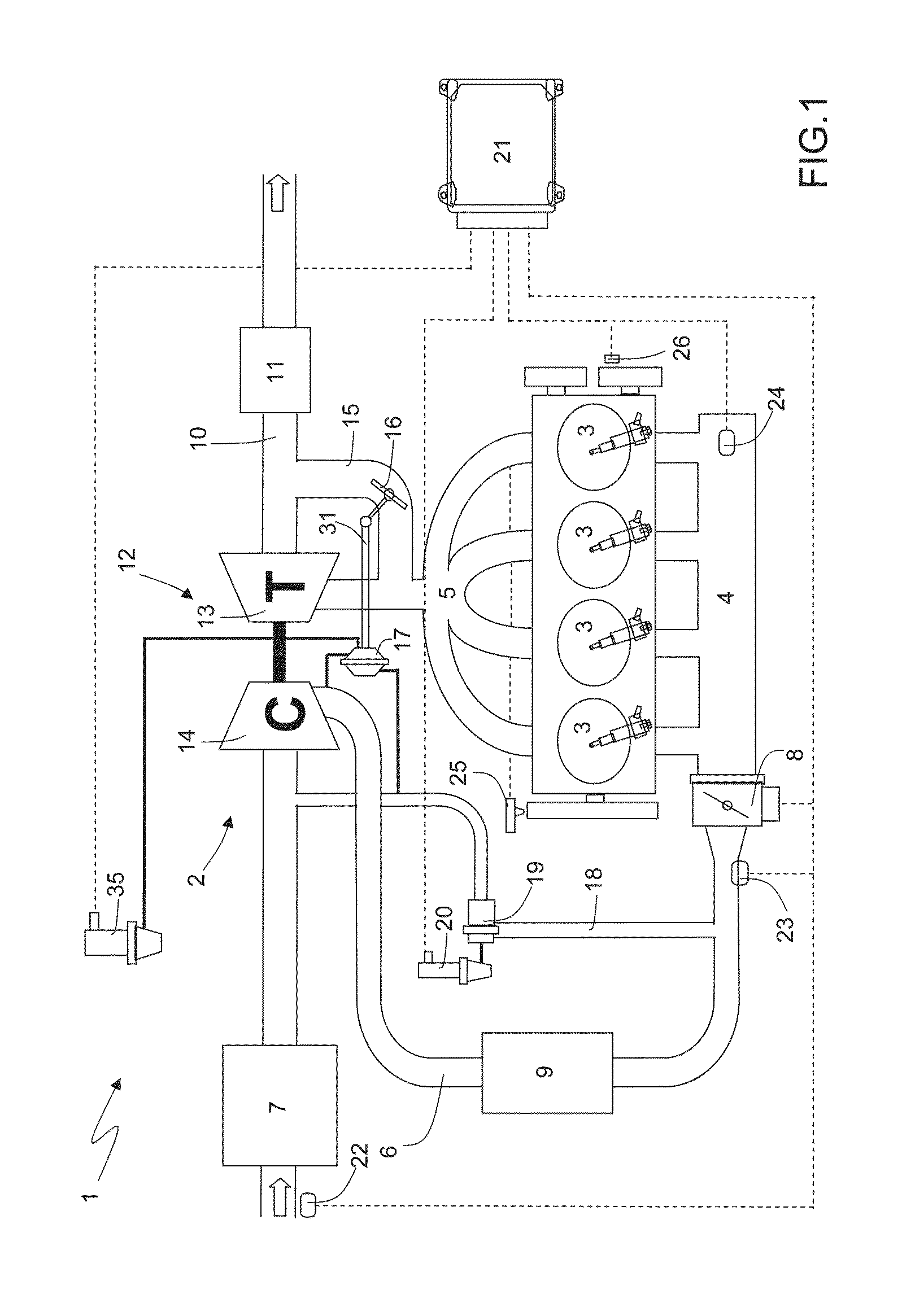
[0016]FIG. 1 is a schematic view of an internal combustion engine turbocharged by means of a turbocharger and equipped with a control unit that implements the method for correcting the reduced mass flow rate of a compressor, the subject of the present inventio...


PUM


Abstract

A method for correcting the reduced mass flow rate of a compressor in an internal combustion engine turbocharged by means of a turbocharger provided with a turbine and with a compressor; the internal combustion engine comprising an intake manifold and an exhaust manifold, and being set up to allow the passage of air from the intake manifold to the exhaust manifold; the method comprising determining, in a design stage, a control law that provides an objective opening of a control actuator of the wastegate as a function of an actual supercharging pressure and of a reduced mass flow rate of the compressor; and correcting the reduced mass flow rate of the compressor as a function of the enthalpy of a gas mixture flowing through the turbine of the turbocharger.

Description

TECHNICAL FIELD[0001]The present invention relates to a method for correcting the reduced mass flow rate of a compressor in an internal combustion engine turbocharged by means of a turbocharger.PRIOR ART[0002]As is known, some internal combustion engines are provided with a turbocharger supercharging system, which may increase the power developed by the engine by exploiting the enthalpy of exhaust gases to compress the air aspirated by the engine and thus increase the volumetric intake performance.[0003]A turbocharger supercharging system comprises a turbocharger equipped with a turbine, which is arranged along an exhaust pipe to rotate at high speed under the propelling force of exhaust gases expelled from the engine, and with a compressor, which is driven in rotation by the turbine and is arranged along the air intake duct to compress the air aspirated by the engine. In a turbocharger supercharging system, it is necessary to the keep the operating range of the turbocharger within ...

Claims


Application Information

Patent Timeline
Patent Type & Authority Applications(United States)
IPC IPC(8): F02B37/12F02D23/00
CPCF02B37/127F02B2037/122F02D23/00F02D41/0087F02B37/16F02B37/18F02D41/0007F02D41/1401F02D2041/1409F02D2041/141F02D2041/1418F02D2200/0402F02D2200/0406F02D2200/0414F02D2200/703F02B37/162Y02T10/12
Inventor PANCIROLI, MARCO
Owner MARELLI EURO SPA
Why Eureka
Try Eureka