
System and Method for Controlling Temperature and Humidity in Multiple Spaces using Liquid Desiccant

a technology of desiccant and multiple spaces, applied in the field of temperature and humidity control, can solve the problems of not always the case, people may still feel uncomfortable, and the air conditioning system does not operate, so as to improve the comfort of occupants in a building

Active Publication Date: 2015-03-12
MITSUBISHI ELECTRIC RES LAB INC
View PDF22 Cites 1 Cited by
  • Summary
  • Abstract
  • Description
  • Claims
  • Application Information

AI Technical Summary

Benefits of technology

The patent text talks about a system that uses liquid desiccants to cool and dehumidify air in buildings. The system includes a main unit and multiple smaller units that work together to control the environment in different rooms. The liquid desiccant is processed by the conditioning units and then returned back to the main unit for reconditioning. The technical effect is that by circulating the liquid desiccant through multiple units without changing its concentration, the system becomes more energy efficient.

Problems solved by technology

When the temperature is low and the humidity is high, such air-conditioning systems do not operate because the temperature is within an acceptable range.
While high humidities often accompany high temperatures, this is not always the case.
In some climates, summer air temperatures may not be especially high, but people may still feel uncomfortable because of the high humidity.
Building maintenance concerns also justify humidity control, as building structures that are subject to high humidity conditions are prone to damage by mildew and mold.
Systems incorporating vapor-compression air-conditioning equipment can be used to dehumidify spaces, but these systems are inherently quite inefficient in their use of energy.
This process of first dehumidifying and then reheating the process air consumes a great deal of energy.
As the desiccant in a dehumidifier accumulates water, the ability of the desiccant to continue removing water from the air decreases, rendering the desiccant less effective.
A fundamental problem of systems using solid desiccant is that the dried air exiting the dehumidification component is warmer than the input moist air.
This additional heat must also be removed from the air stream by the air-conditioning system, reducing the energy efficiency of the overall air-conditioning process.
While various architectures for a space conditioning system can provide the desired operating conditions, the constraints placed on the system operation by the architecture may cause many of these systems to operate inefficiently.

Method used


Image

  • System and Method for Controlling Temperature and Humidity in Multiple Spaces using Liquid Desiccant
  • System and Method for Controlling Temperature and Humidity in Multiple Spaces using Liquid Desiccant
  • System and Method for Controlling Temperature and Humidity in Multiple Spaces using Liquid Desiccant

Examples


Embodiment Construction

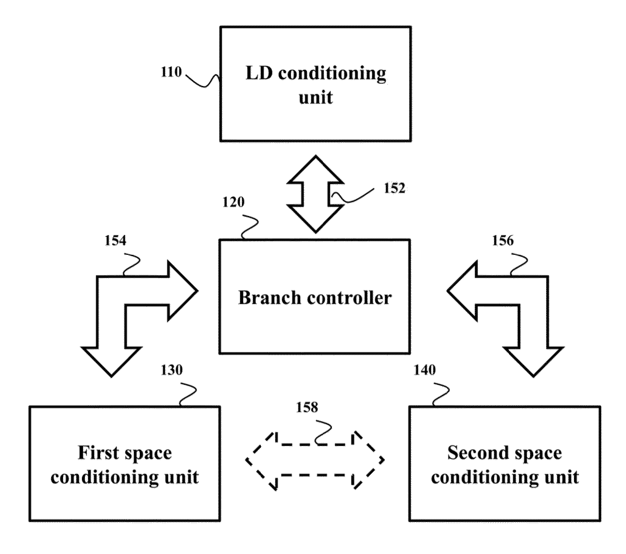
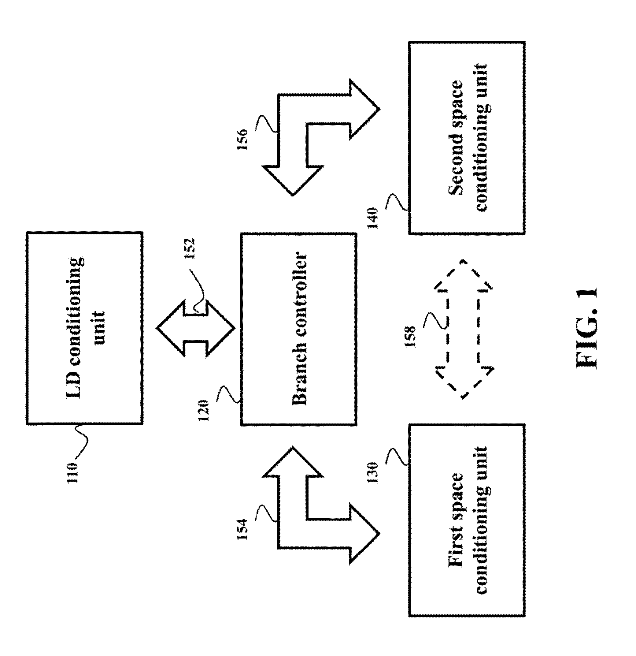
[0032]FIG. 1 shows a block diagram of a system for temperature and humidity control according to one embodiment of the invention. The system includes a liquid desiccant (LD) conditioning unit 110 for changing a temperature and a concentration of a liquid desiccant. For example, the liquid desiccant conditioning unit can include a regenerator and multiple heat exchangers for changing the temperature and the concentration of the liquid desiccant (not shown). The system also includes multiple space conditioning units for controlling indoor environments using the liquid desiccant. For example, the system can include a first space conditioning unit 130 for controlling a first environment and a second space conditioning unit 140 for controlling a second environment. The first and the second environments are usually physically separated from each other, e.g., in separate rooms in a building. The system also includes a branch controller 120 for redirecting the liquid desiccant received from...


PUM


Abstract

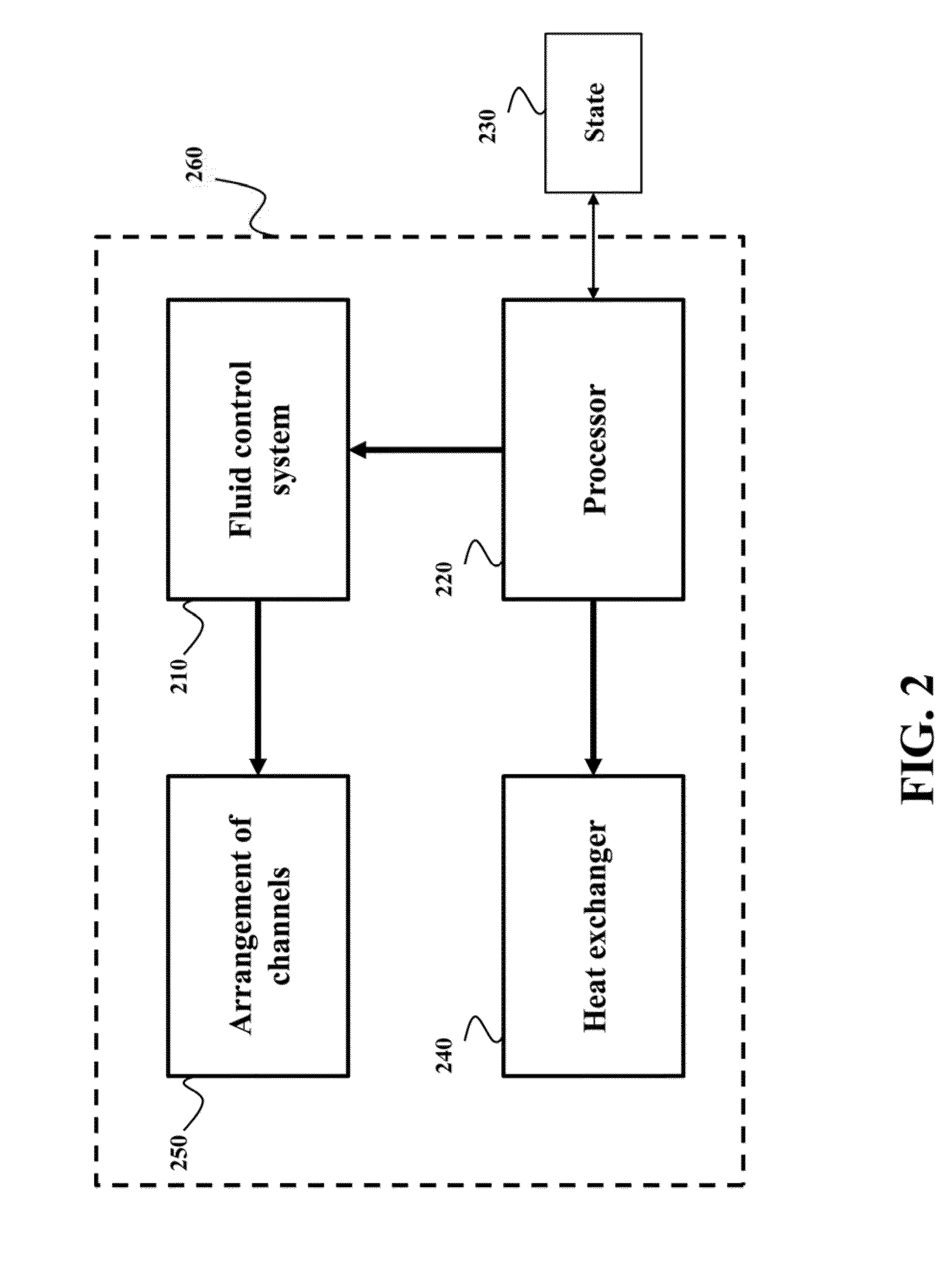
A branch controller operates with a system for temperature and humidity control. The branch controller includes a fluid control system for controlling a flow of the liquid desiccant in an arrangement of channels forming a first path for exchanging the liquid desiccant between a liquid desiccant conditioning unit and at least a first space conditioning unit and a second path for directing the liquid desiccant received from the first space conditioning unit to a second space conditioning unit. The branch controller includes a processor for comparing operational conditions of the first space conditioning unit and the second space conditioning unit. The processor selects between the first path and the second path based on the comparison and commands the fluid control system to control the flow of the liquid desiccant according to the selected path.

Description

FIELD OF THE INVENTION[0001]This invention relates generally to temperature and humidity control, and more particularly, to controlling temperature and humidity in multiple spaces using liquid desiccants.BACKGROUND OF THE INVENTION[0002]The comfort of the occupants in buildings depends on the temperature and the humidity of occupied spaces. The temperature in the occupied space can be affected by factors such as the outdoor air conditions, a change in the number of occupants in the space, or devices in the space that are either producing or removing heat. Similarly, the humidity in the occupied space can be affected by outdoor air conditions, the accumulation of water vapor in the space, or processes that deplete water from the air or exhaust water vapor into the air. In the field of air-conditioning, heat sources that cause the temperature to change are typically called sensible loads, while the sources and sinks of water vapor that cause the humidity to change are called latent lo...

Claims


Application Information

Patent Timeline
Patent Type & Authority Applications(United States)
IPC IPC(8): F25B15/00
CPCF25B15/00F24F3/065F24F3/1417
Inventor LAUGHMAN, CHRISTOPHERBURNS, DANIEL J.BORTOFF, SCOTT A.WATERS, RICHARD C.
Owner MITSUBISHI ELECTRIC RES LAB INC
Learn More