
Turbulent jet ignition pre-chamber combustion system for spark ignition engines

a combustion system and engine technology, applied in the field of ignition systems, can solve the problems that the cost of adding cannot be justified, and achieve the effects of high-peak thermal efficiency, high-drive cycle (part load) fuel economy, and promotion of flame quenching

Active Publication Date: 2015-03-12
MAHLE POWERTRAIN
View PDF8 Cites 55 Cited by
  • Summary
  • Abstract
  • Description
  • Claims
  • Application Information

AI Technical Summary

Benefits of technology

The turbulent jet ignition pre-chamber combustion system described in the patent improves engine performance by promoting flame quenching and reducing heat loss. It also reduces emissions and achieves high-drive cycle fuel economy improvements with a combination of combustion improvements, reduced heat loss, and reduced engine throttling at part-load. The system can be used in existing engines without requiring any modification to the hardware, and it is compatible with any carbon-based fuel. Overall, the system provides a "bolt on" fix for any spark ignition engine that works with pre- or post-production models and ensures compliance with current and future emission regulations.

Problems solved by technology

However, internal combustion engines having pre-chambers have not been widely commercially accepted in the automotive industry, typically because they suffer from higher costs and complexity and sometimes without any significant increase in fuel economy or reduction in pollutants, such that the added cost cannot be justified.

Method used


Image

  • Turbulent jet ignition pre-chamber combustion system for spark ignition engines
  • Turbulent jet ignition pre-chamber combustion system for spark ignition engines
  • Turbulent jet ignition pre-chamber combustion system for spark ignition engines

Examples


Embodiment Construction

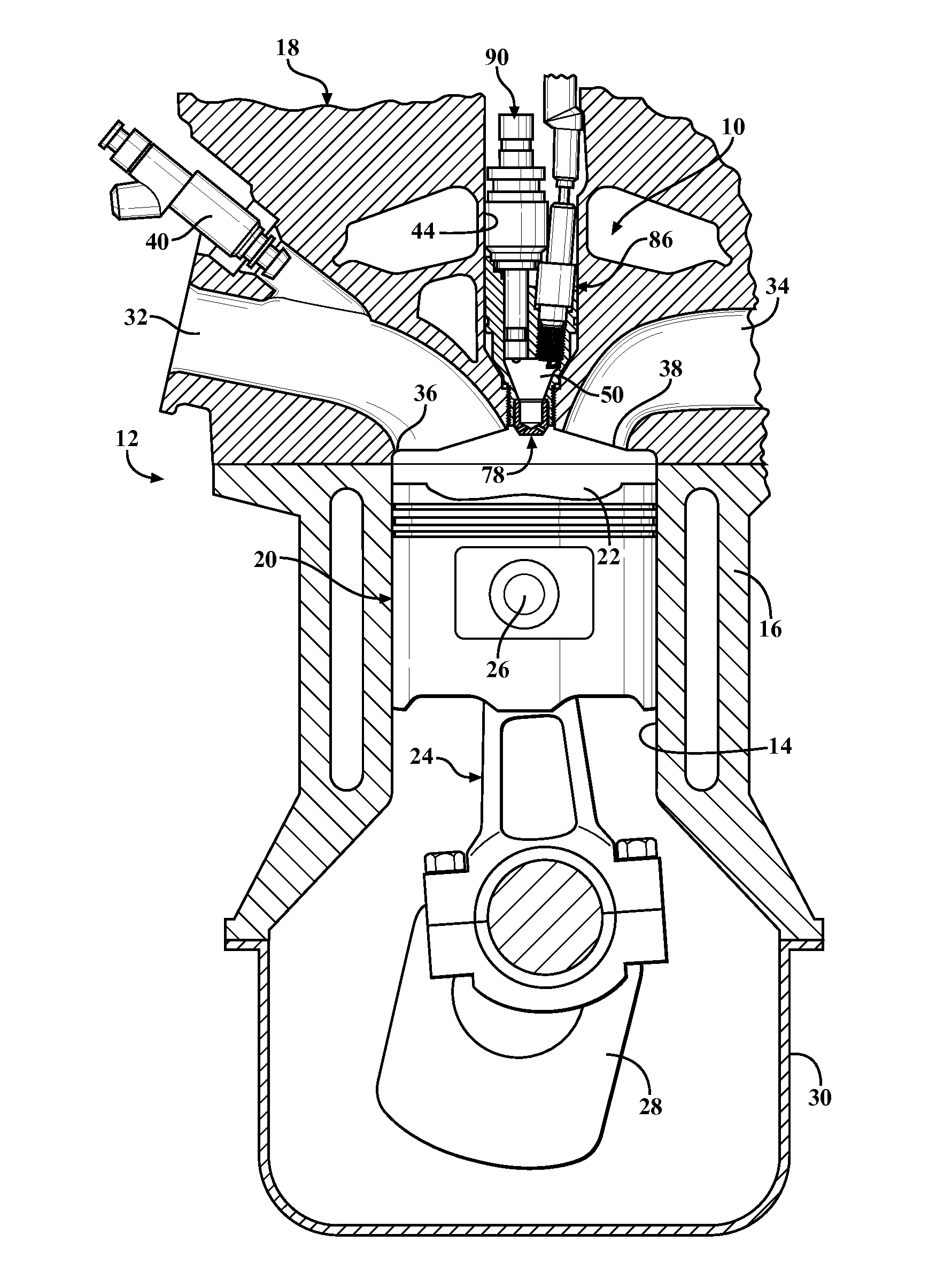
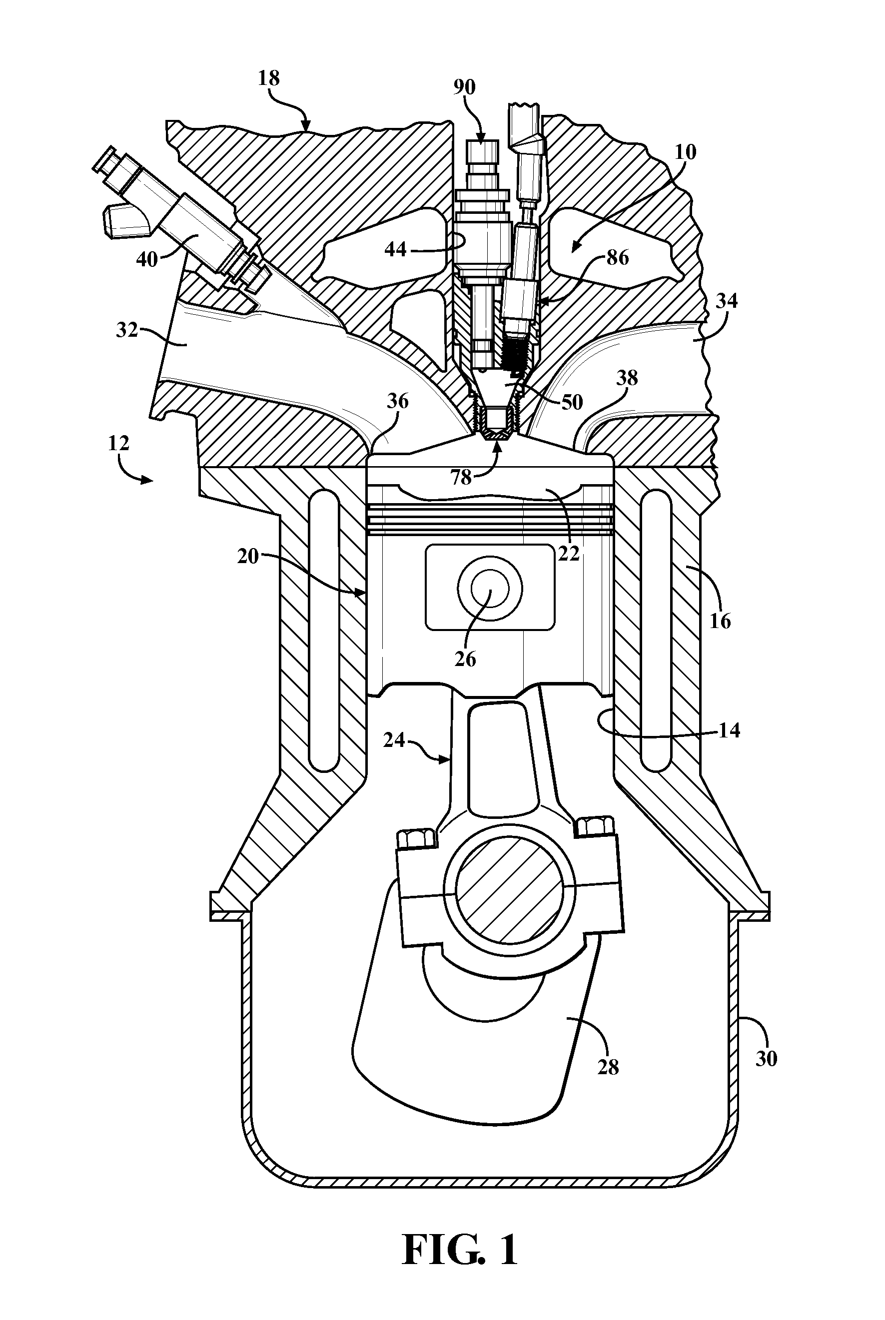
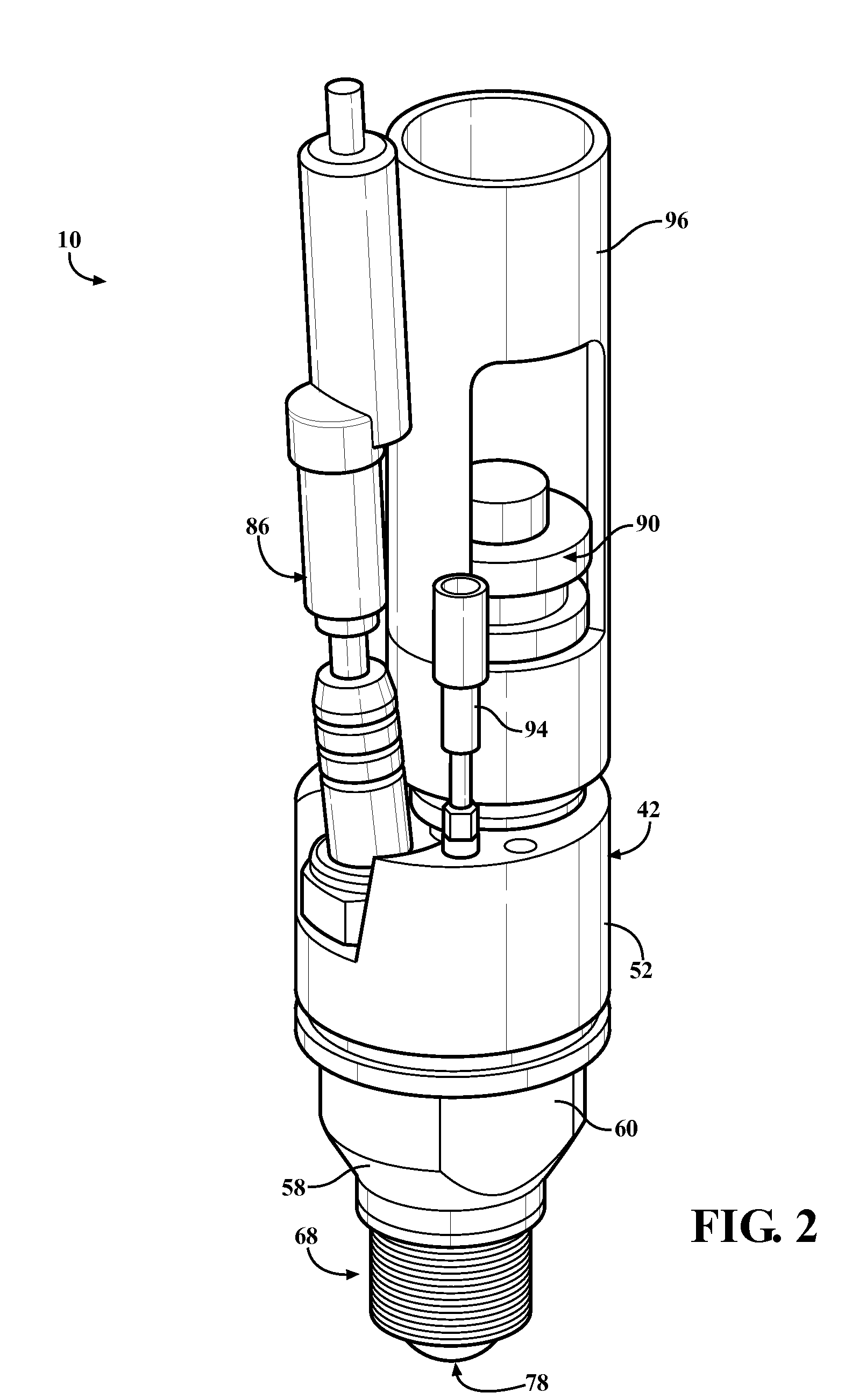
[0029]The present invention overcomes the disadvantages in the related art in an ignition system, generally indicated at 10 in FIGS. 1-6, where like numerals are used to designate like structure throughout the drawings. As shown in FIG. 1, the present invention is particularly adapted for use in an internal combustion engine, generally indicated at 12. In this case, the ignition system 10 of the present invention is illustrated in connection with a single cylinder 14 of an internal combustion engine 12. Those having ordinary skill in the art will appreciate that the engine 12 illustrated in FIG. 1 is but one of the many configurations of an internal combustion engine with which the present invention may be employed. By way of example, the present invention may be employed in a two-stroke or four-stroke engine. In addition, the ignition system 10 may also be employed in a multiple-cylinder engine where the cylinders may be arranged in an inline, V-shaped, or flat manner, or any other...


PUM


Abstract

An ignition system for an internal combustion engine having at least one combustion chamber where the ignition system includes a housing, an ignition device, an injector, and a pre-chamber having a nozzle disposed spaced from the proximal portion of the pre-chamber. The igniter portion of the ignition device and the nozzle of the injector are operatively supported in the proximal portion of the pre-chamber and disposed flush therewith. The igniter portion ignites the fuel in pre-chamber such that partially combusted pre-chamber products are forced through orifices in the pre-chamber nozzle and extinguish, but dispersed through the combustion chamber so as to ignite the main fuel charge therein.

Description

CROSS REFERENCE TO RELATED APPLICATIONS[0001]This application is a continuation-in-part of U.S. patent application entitled “Turbulent Jet Ignition Pre-Chamber Combustion System for Spark Ignition Engines,” having Ser. No. 13 / 286,638, and filed on Nov. 1, 2011, and claims the benefit of U.S. provisional patent application entitled “Turbulent Jet Ignition Pre-Chamber Combustion System for Spark Ignition Engines,” having Ser. No. 61 / 408,892, and filed on Nov. 1, 2010.BACKGROUND OF THE INVENTION[0002]1. Field of the Invention[0003]The present invention relates, generally, to an ignition system and, more specifically, to an ignition system for an internal combustion engine having at least one combustion chamber with an injector, ignition device, and a pre-chamber that may be employed to ignite a small charge, which is then used to ignite the main air fuel charge in the main combustion chamber of the internal combustion engine.[0004]2. Description of the Related Art[0005]Internal combust...

Claims


Application Information

Patent Timeline
IPC IPC(8): F02B19/10
CPCY02T10/125F02B19/1057F02B19/12F02P9/007F02P5/045F02D41/0027F02B19/108F02M57/06F02P5/04F02P13/00Y02T10/12
Inventor BUNCE, MICHAELBLAXILL, HUGHATTARD, WILLIAM
Owner MAHLE POWERTRAIN
Learn More