Duct-type indoor unit of air conditioner

a technology of indoor unit and air conditioner, which is applied in the direction of heating type, ventilation system, lighting and heating apparatus, etc., can solve the problems of large number of components, difficult to and difficult to reduce the operating power of the fan, so as to reduce the number of components and improve the efficiency of the fan

Active Publication Date: 2015-03-12
DAIKIN IND LTD
View PDF26 Cites 14 Cited by
  • Summary
  • Abstract
  • Description
  • Claims
  • Application Information

AI Technical Summary

Benefits of technology

[0007]An object of the present invention is to provide a duct-type indoor unit of an air conditioner with a reduced number of components and improved fan efficiency.

Problems solved by technology

One problem with the sirocco fan used in such a duct-type indoor unit of an air conditioner is that it has a large number of components because of the fan casing.
Another problem with the sirocco fan is that it is difficult to improve the fan efficiency without the fan casing, because of the structure wherein air is blown out after first being sucked into the fan casing.
This leads to yet another problem that it is difficult to reduce operating power of the fan while securing a necessary level of static pressure and flow amount.

Method used


Image

  • Duct-type indoor unit of air conditioner
  • Duct-type indoor unit of air conditioner
  • Duct-type indoor unit of air conditioner

Examples


Embodiment Construction

[0016]Hereinafter, a duct-type indoor unit of an air conditioner according to one embodiment of the present invention will be described with reference to the drawings.

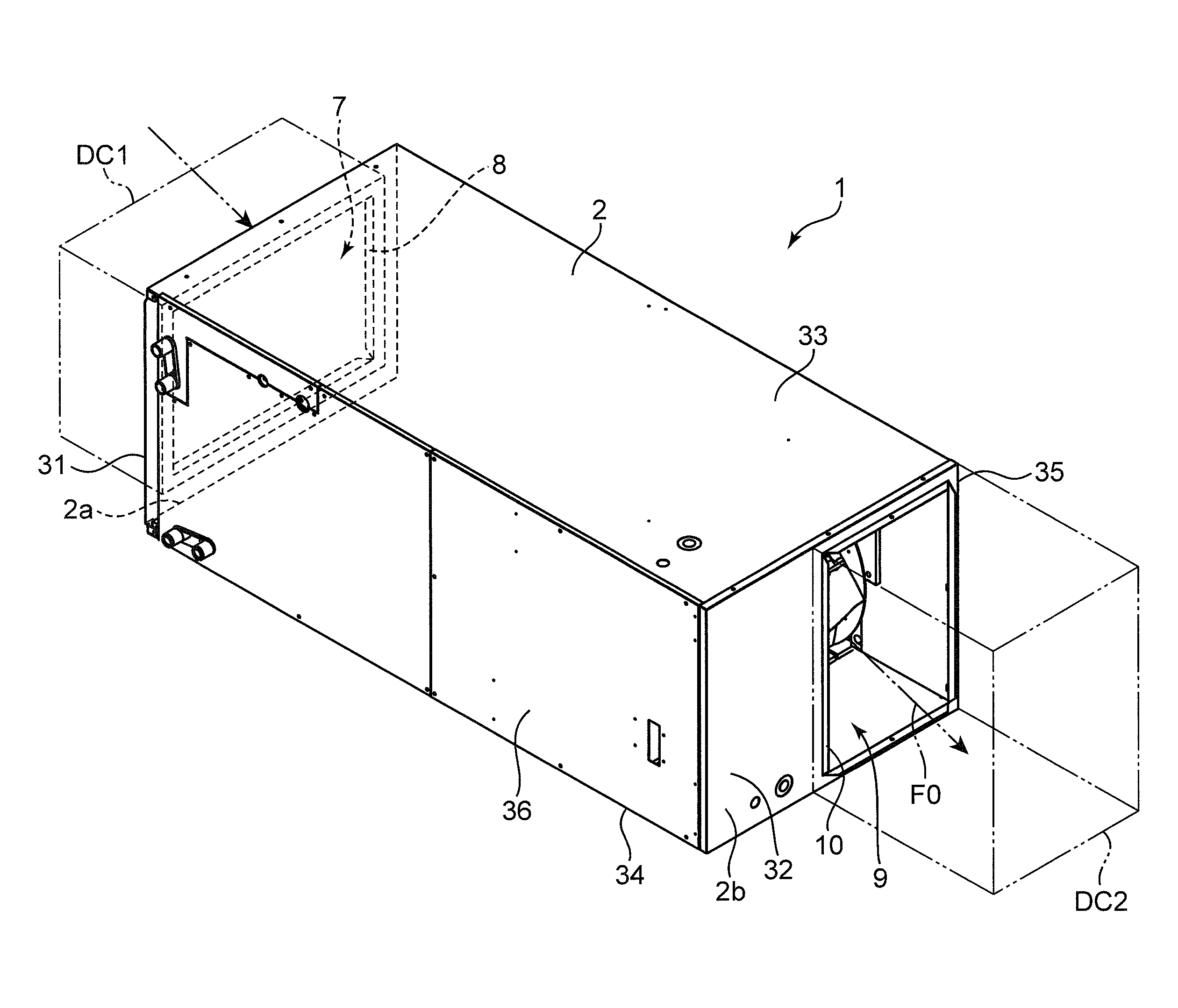
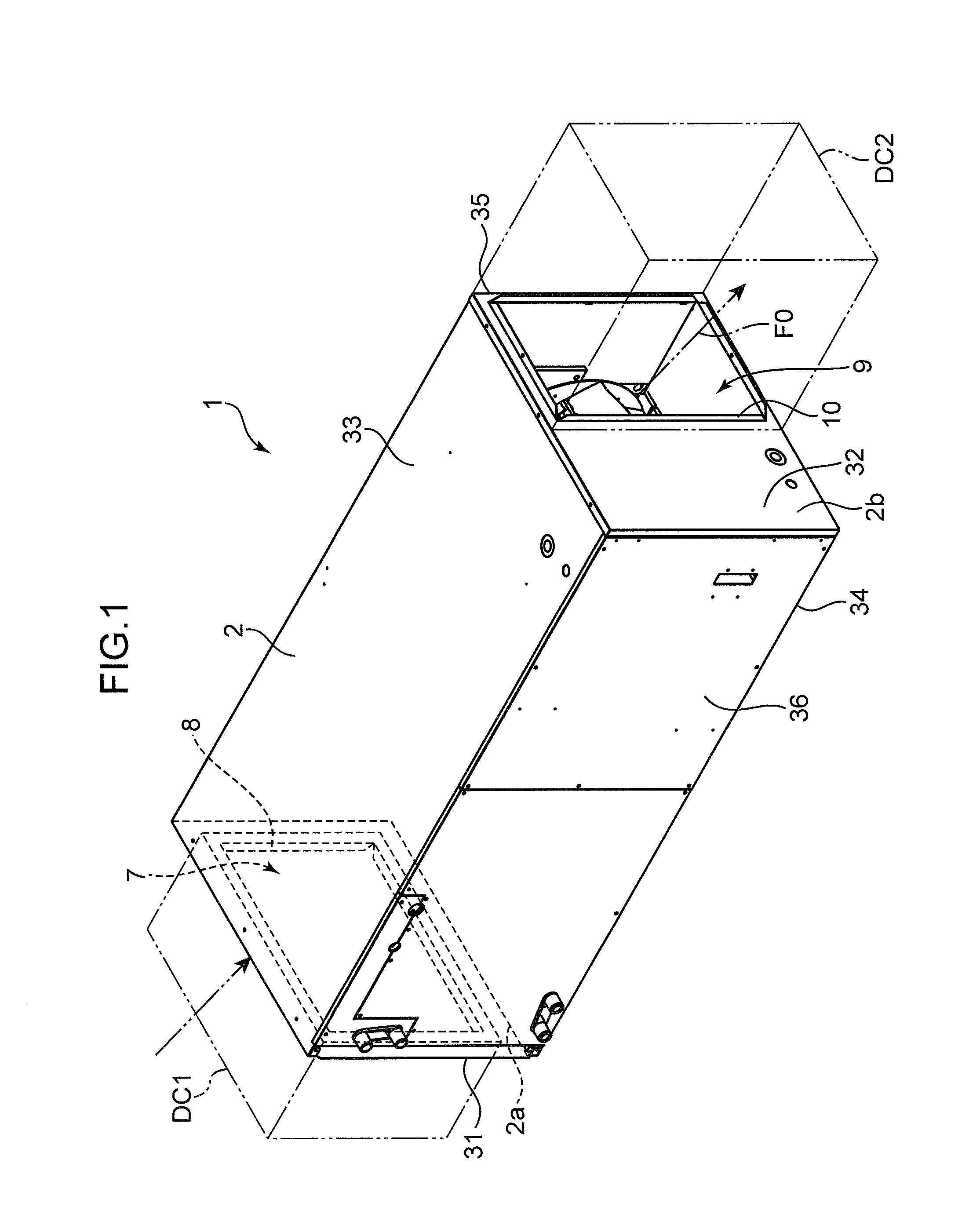
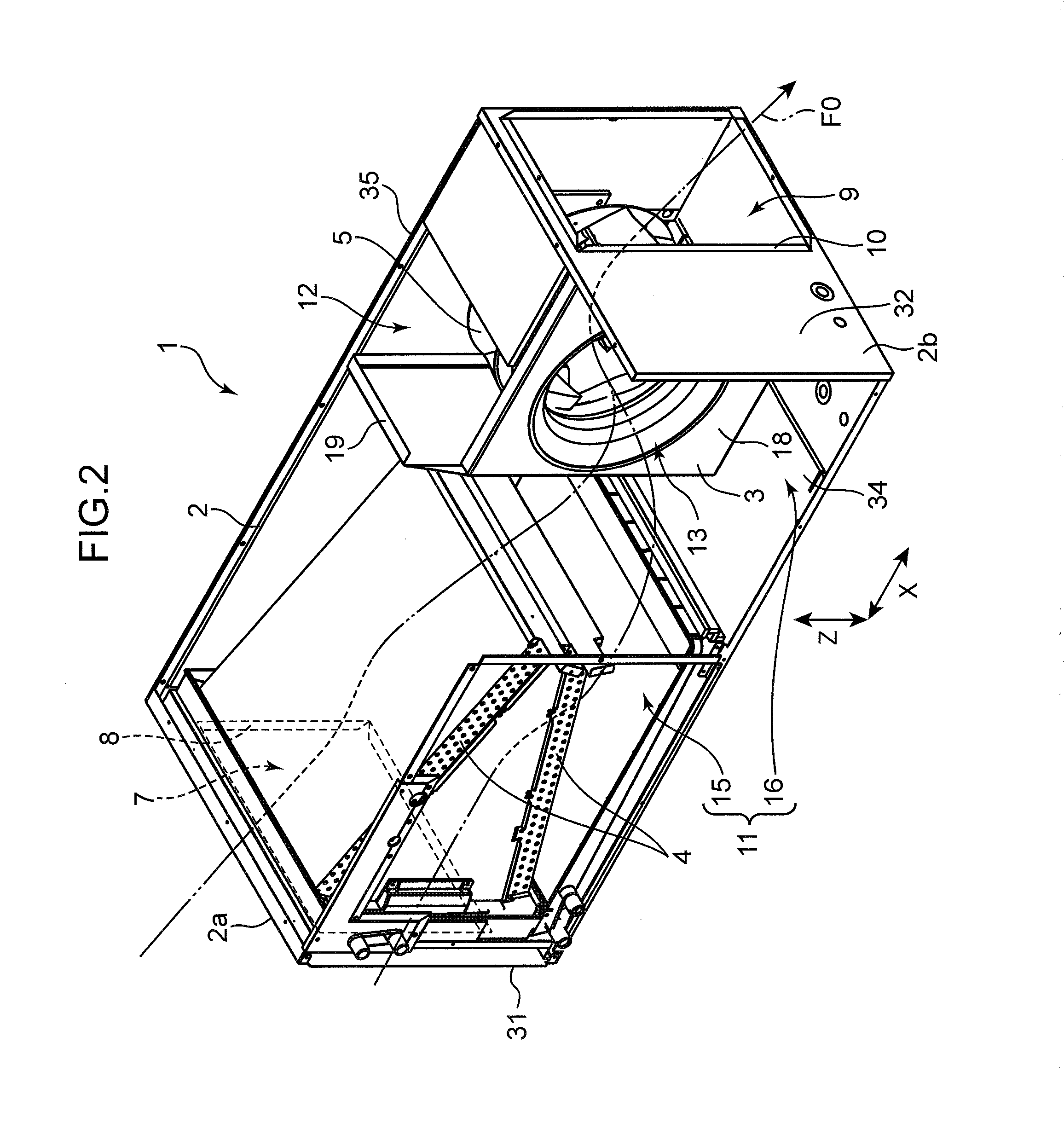
[0017]The duct-type indoor unit 1 of an air conditioner shown in FIG. 1 to FIG. 4 includes a casing 2, a partition member 3 that divides the interior of the casing 2 into two spaces (i.e., first space 11 and second space 12), a pair of heat exchangers 4 housed in the first space 11 (more specifically, in a heat exchange chamber 15 thereof), and a centrifugal fan 5 and a fan motor 6 housed in the second space 12. The fan motor 6 drives the impeller 21 of the centrifugal fan 5 to rotate.

[0018]The casing 2 includes a front plate 31, a rear plate 32, an upper plate 33, a lower plate 34, a first side plate 35, and a second side plate 36. These plates 31 to 36 constitute the elongated rectangular parallelepiped casing 2. The front plate 31 and the rear plate 32 are spaced apart from each other in a longitudinal direction of ...


PUM


Abstract

The duct-type indoor unit of an air conditioner includes: a casing including a first surface and a second surface opposing each other, an inlet duct connection part which is formed in the first surface and to which an inlet duct is connected, and an outlet duct connection part which is formed in the second surface and to which an outlet duct is connected; a partition member partitioning interior of the casing into a first space on an inlet side and a second space on an outlet side, the partitioning member having an opening communicating the first space with the second space; a heat exchanger arranged inside the first space; and a centrifugal fan having an impeller with backward curved blades, the impeller being positioned inside the second space to suck in air in the first space through the opening. The impeller has a rotating shaft parallel to the first surface.

Description

TECHNICAL FIELD[0001]The present invention relates to a duct-type indoor unit of an air conditioner.BACKGROUND ART[0002]Duct-type indoor units of air-conditioners installed in the ceiling for air-conditioning of the interior of a building or the like have been known. Japanese Patent Application Laid-open No. 2003-42480, for example, describes a duct-type indoor unit of an air conditioner that is concealed in the ceiling. The duct-type indoor unit includes a main body casing having an inlet and an outlet arranged opposite each other, and a heat exchanger and a fan arranged along a straight line between the inlet and the outlet. An inlet duct and an outlet duct are connected to the inlet and outlet of the main body casing, respectively.[0003]The duct-type indoor unit of the air conditioner described in Japanese Patent Application Laid-open No. 2003-42480 has respective ducts connected to the inlet side and outlet side when in use. The fluid resistance thus tends to be high at the inle...

Claims


Application Information

Patent Timeline
Patent Type & Authority Applications(United States)
IPC IPC(8): F28D1/02F24F7/007F24F1/0047
CPCF24F7/007F28D1/02F24F13/20F24F1/0022F24F1/0047F24F2013/205F24F13/30F24F13/08F24F1/0059
Inventor KASHIHARA, TAKASHIYAMASAKI, TAKAHIROMARUYAMA, KANAME
Owner DAIKIN IND LTD
Why Eureka
Try Eureka