
Interior permanent magnet machine having offset rotor sections

a permanent magnet machine and offset technology, applied in the field of electric machines, can solve the problems of ipm machines suffering from both a manufacturing and a technical (i.e., electromechanical) shortcoming, damage to rotors, gearboxes, and/or mechanical systems, etc., and achieve the effect of more efficient manufacturing and more technical efficiency

Active Publication Date: 2015-03-12
WESTINGHOUSE AIR BRAKE TECH CORP
View PDF10 Cites 18 Cited by
  • Summary
  • Abstract
  • Description
  • Claims
  • Application Information

AI Technical Summary

Benefits of technology

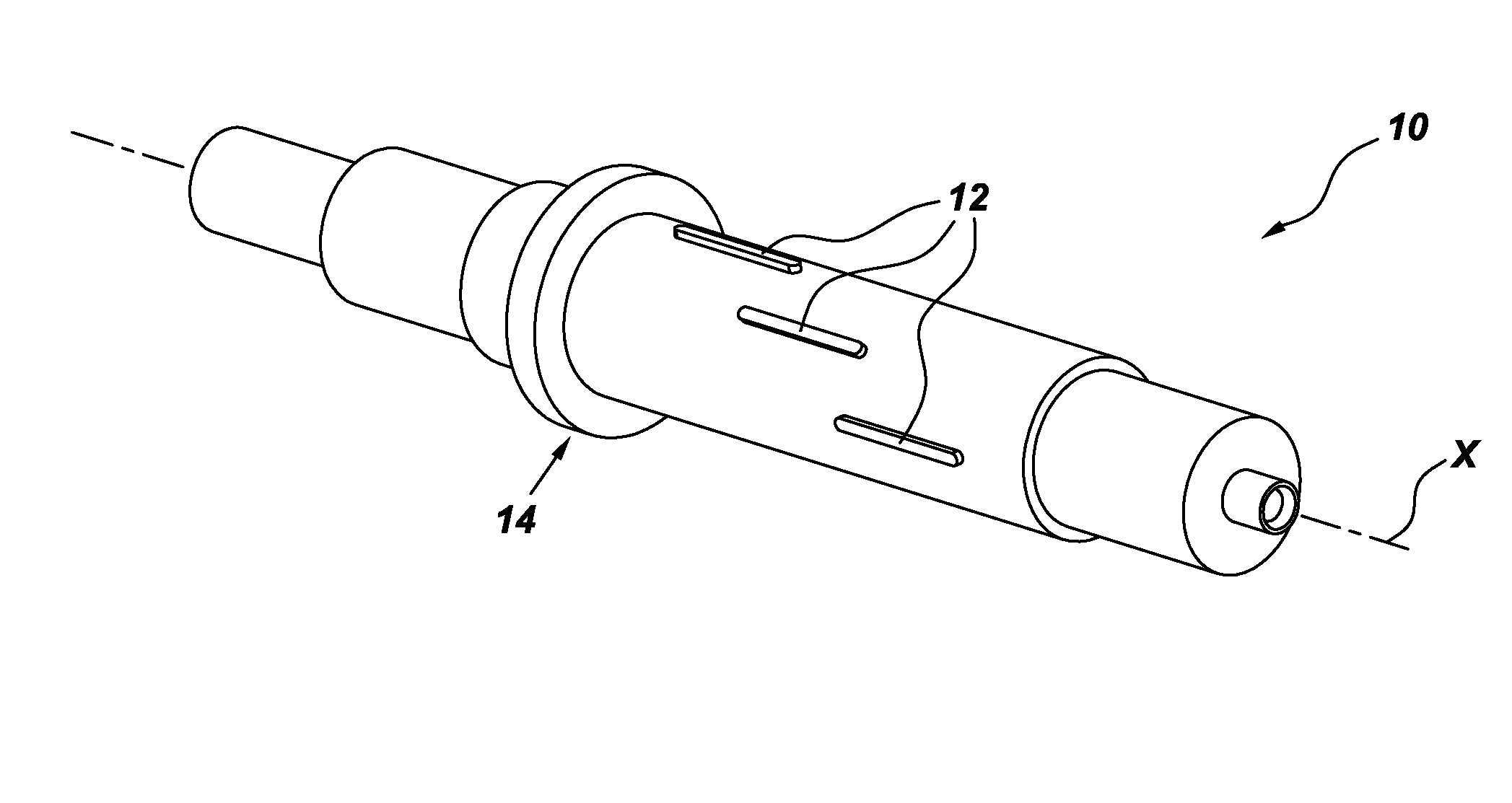
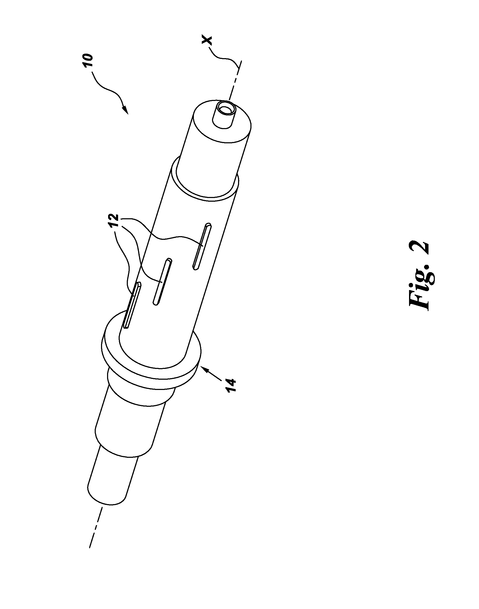
The present invention is about improving electric machines, like IPM machines and Synchronous Reluctance motors, to make them more efficient and effective. Specifically, the invention includes offset rotor sections in these machines. This results in better performance and more efficient operation. The invention also includes components and assemblies that support the offset features of these electric machines. For example, a vehicle like an underground mining vehicle may use these improved motors for compact traction.

Problems solved by technology

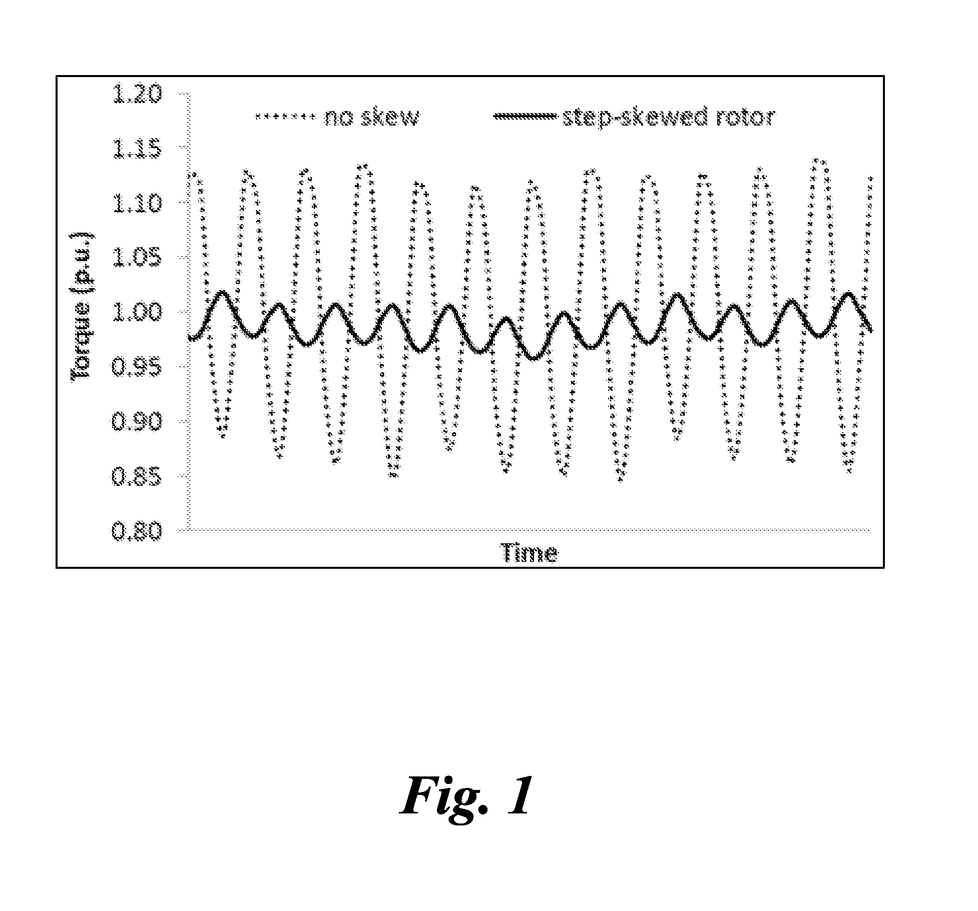
The technical problem addressed in this patent text is the need to improve the performance and efficiency of electric machines, particularly those used in underground mining vehicles, while also reducing complexity and cost. Current methods of reducing torque ripple, which can damage the rotor, gearbox, and mechanical system connected to the machine, suffer from either increased manufacturing costs or decreased efficiency. The invention aims to address these issues by improving the design and manufacturing of electric machines.

Method used


Image

  • Interior permanent magnet machine having offset rotor sections
  • Interior permanent magnet machine having offset rotor sections
  • Interior permanent magnet machine having offset rotor sections

Examples


Embodiment Construction

[0025]Unless defined otherwise, technical and scientific terms used herein have the same meaning as is commonly understood by one of ordinary skill in the art with respect to the presently disclosed subject matter. The terms “first”, “second”, and the like, as used herein do not denote any order, quantity, or importance, but rather are used to distinguish one element from another. The terms “a”, “an”, and “the” do not denote a limitation of quantity, but rather denote the presence of at least one of the referenced item, and the terms “front”, “back”, “bottom”, and / or “top”, unless otherwise noted, are used for convenience of description only, and are not limited to any one position or spatial orientation.

[0026]If ranges are disclosed, the endpoints of all ranges directed to the same component or property are inclusive and independently combinable (e.g., ranges of “up to about 25 wt. %,” is inclusive of the endpoints and all intermediate values of the ranges of “about 5 wt. % to abou...


PUM

PropertyMeasurementUnit
Forceaaaaaaaaaa
Angleaaaaaaaaaa
Torqueaaaaaaaaaa

Abstract

A motor rotor assembly that includes multiple motor rotor sections and a rotor bar that extends through the motor rotor sections, such that the rotor bar and the motor rotor sections are configured such that the rotor sections are step-skewed, or continuously skewed, from each other. The assembly may be used in an IPM or Synchronous Reluctance motor; and, the motor rotor sections may be of solid core or laminations. Various assembly components, IPM and Synchronous Reluctance motors, and methods of construction/assembly are also disclosed. The present invention has been described in terms of specific embodiment(s), and it is recognized that equivalents, alternatives, and modifications, aside from those expressly stated, are possible and within the scope of the appending claims.

Description


Claims


Application Information

Patent Timeline
Owner WESTINGHOUSE AIR BRAKE TECH CORP
Learn More