Battery changing system and method

a battery and changing system technology, applied in the direction of battery/cell propulsion, transportation items, vehicle maintenance, etc., can solve the problems of inconvenient battery replacement, time-consuming and labor-intensive, undulating and rough surface over which vehicles move during mining operations, etc., to achieve the effect of decreasing length and increasing length

Active Publication Date: 2015-03-12
GE GLOBAL SOURCING LLC
View PDF9 Cites 45 Cited by
  • Summary
  • Abstract
  • Description
  • Claims
  • Application Information

AI Technical Summary

Benefits of technology

[0012]In one embodiment, a vehicle (e.g., a mining vehicle) includes a vehicle frame, a haulage assembly, and a battery changing system. The vehicle frame includes at least first and second sub-frame assemblies connected with each other. The haulage assembly can be coupled with the first sub-frame assembly and configured to pick up and transport mined material. The battery changing system can be coupled with the second sub-frame assembly and configured to extend from the vehicle frame and lower to a battery box comprising one or more batteries disposed off-board the vehicle frame. The battery changing system also can be configured to grasp the battery box and lift the battery box onto the vehicle frame.

Problems solved by technology

Electric motors are powered by batteries of various chemistry types, and tend to be comprised of cells which are heavy and not easily maneuvered.
Replacement of the batteries is neither efficient nor easy.
Due to the size and / or weight of the batteries, combined with the tight confines inside the mine, changing batteries in a vehicle can be problematic and time-consuming.
Additionally, the surfaces over which vehicles move during mining operations can be undulating and rough.
Travel over these surfaces can cause abrupt shifts or other jarring actions to the batteries being carried by and / or powering the vehicles.
These shifts or jarring actions can cause the batteries to become dislodged from the vehicles, which poses significant safety risks and / or ceases supply of electric power to the vehicles.
Some currently available underground mining battery-powered vehicles do not have onboard battery changing systems.
This causes more machine downtime during the required battery charging or swapping cycles and additional equipment to maintain.
Another problem with requiring external lifting rigging for battery removal is that this equipment must be moved as the active mine face advances to keep the battery changing area near the working area.
Using a battery changing system as designed for use on mining scoop vehicles could cause additional problems.
Because the vehicle must be able to operate in the confined space of these mines, the overall machine dimensions are limited.
The confined spaces of the mine also cause problems when unloading material from the bucket.
The problem with other known designs is that the hydraulic cylinder(s) used to operate the ejector blade are difficult to extract for replacement or servicing.

Method used


Image

  • Battery changing system and method
  • Battery changing system and method
  • Battery changing system and method

Examples


Embodiment Construction

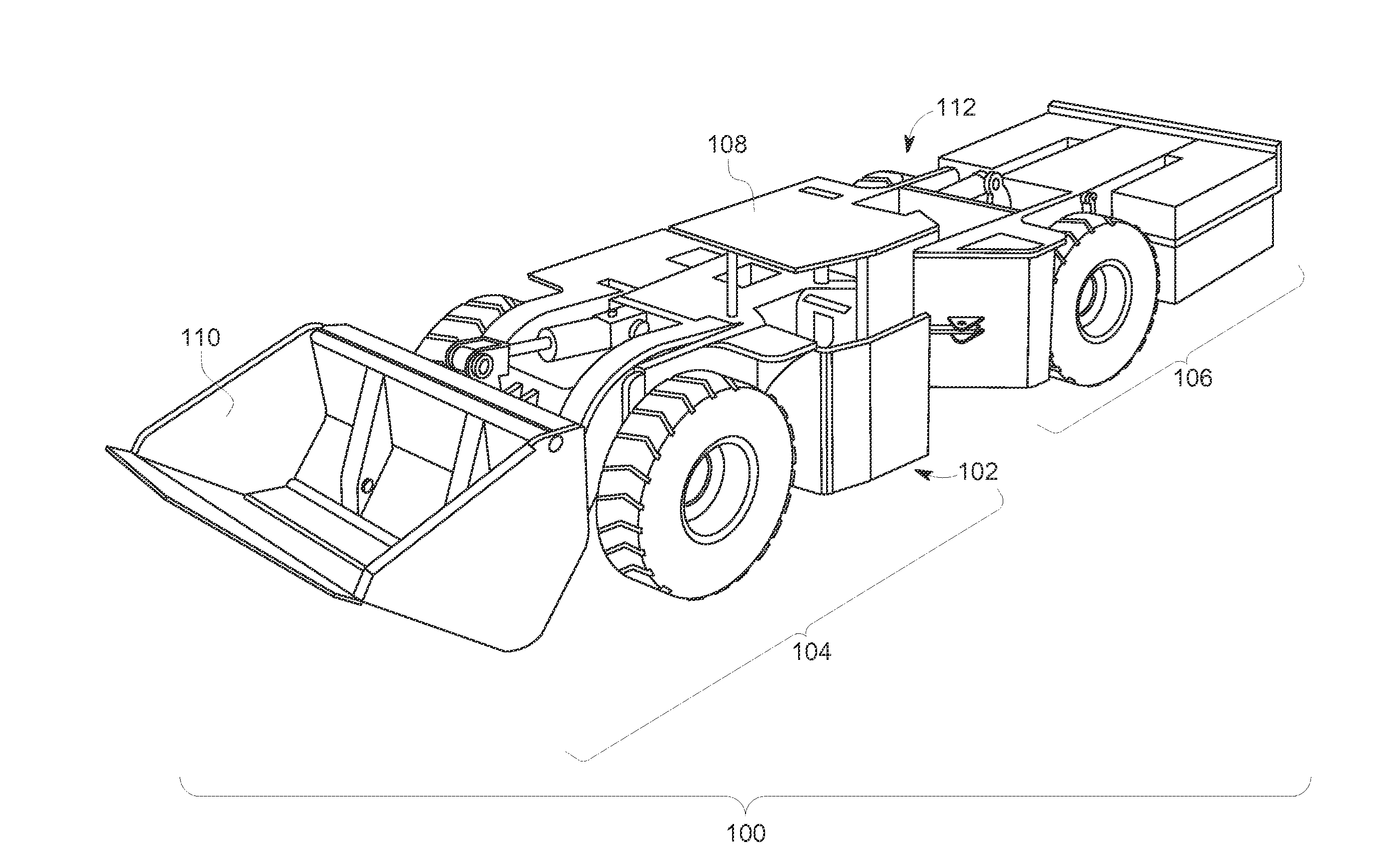
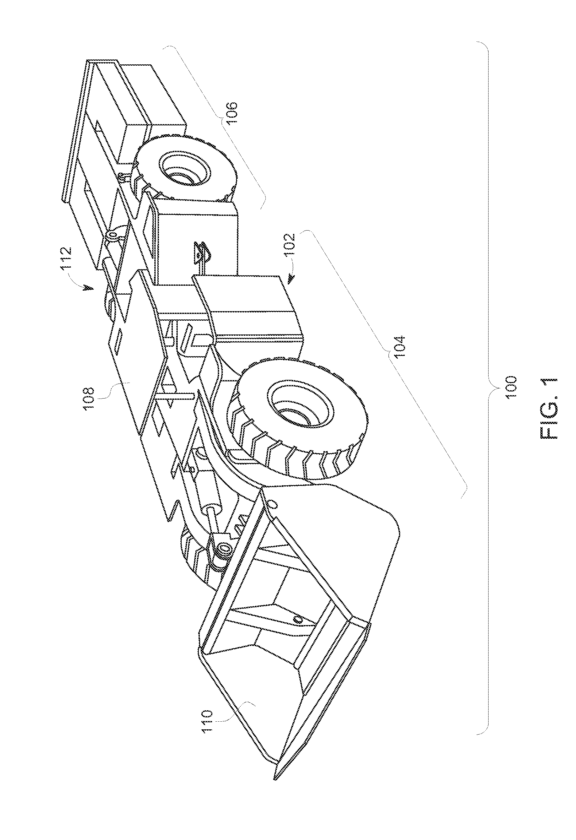
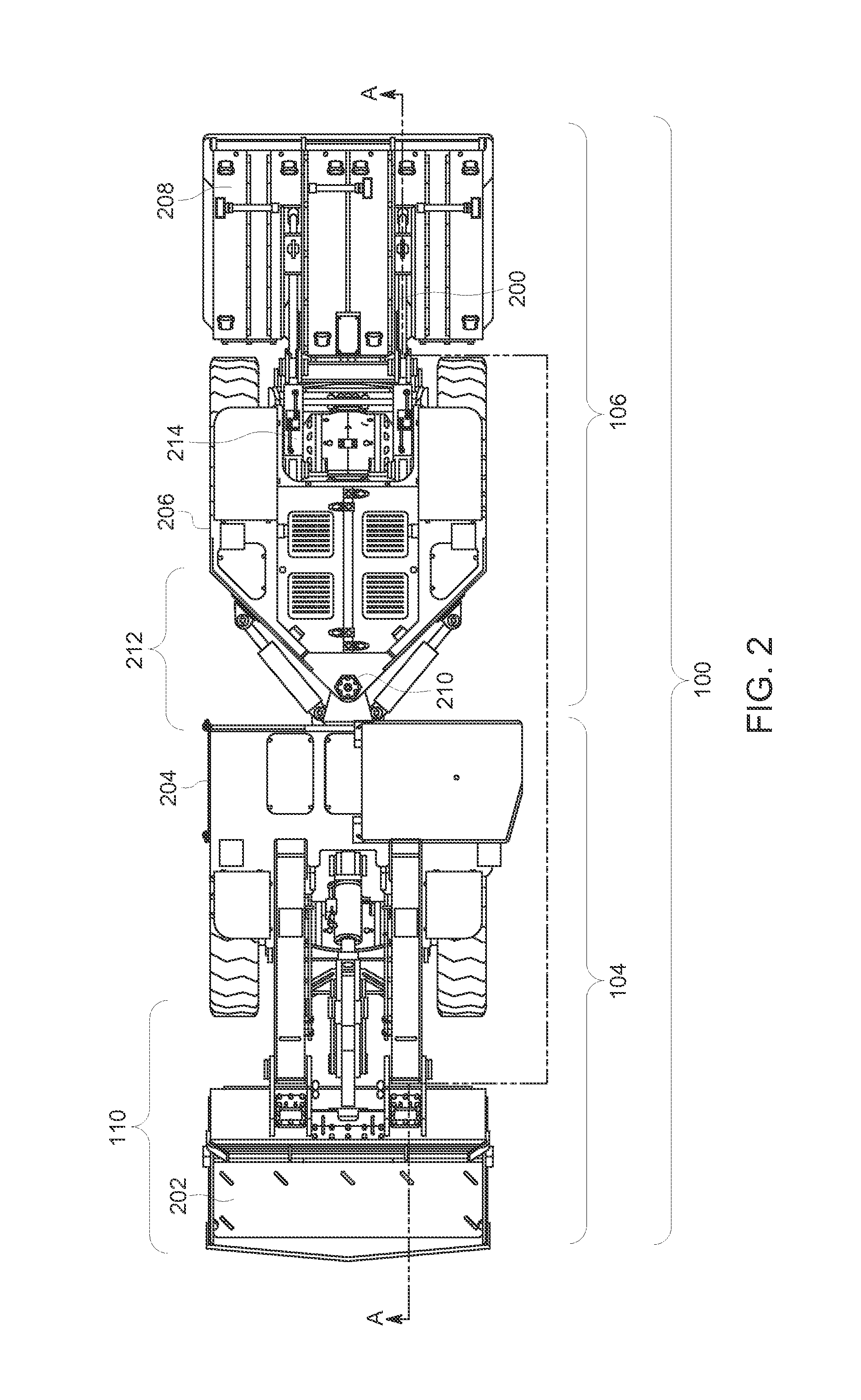
[0035]The subject matter described herein relates to systems and methods for efficiently and quickly exchanging a battery mounted on an off-highway vehicle, such as a load-haul-dump (hereinafter “LHD”) type vehicle for use in underground mines. The systems can include apparatuses for lifting a battery holder, or box containing an electric battery, from ground level (e.g., the surface on which the vehicle is located) to an elevated position so as to transport the battery holder into operative engagement with the vehicle (e.g., connected or interconnected with the vehicle in order to power the vehicle and / or be conveyed by the vehicle to another location).

[0036]In order to lift and / or replace the battery of a vehicle, battery changing systems and methods are described that provide for more efficient lift points than currently known changing systems, improved stability of a battery box or tray that supports and / or encloses battery cells, and ease of “drop and replace” movement in restr...


PUM


Abstract

A battery changing system includes a grasping assembly and an actuation assembly. The grasping assembly is configured to be disposed onboard a vehicle and to engage a battery box having one or more batteries disposed therein. The actuation assembly is configured to move the grasping assembly away from the vehicle toward the battery box. The actuation assembly also is configured to move the grasping assembly into engagement with a securing assembly of the battery box. The actuation assembly is configured to move the grasping assembly back toward the vehicle while the grasping assembly engages the securing assembly of the battery box to lift the battery box onto the vehicle.

Description

CROSS-REFERENCE TO RELATED APPLICATIONS[0001]This application claims priority to U.S. Provisional Application Ser. No. 61 / 876,216, which was filed on 10 Sep. 2013, is titled “Battery Powered OHV With Onboard Battery Changing System And Bucket,” and the entire disclosure of which is incorporated herein by reference.FIELD[0002]The subject matter described herein relates to electric powered systems, such as electrically powered vehicles.BACKGROUND[0003]Mining vehicles utilized in underground mining operations are adapted to accommodate the tight confines of the environment in which the vehicles operate. Narrow passageways, tight turns, low roofs, and small staging or depot areas give rise to vehicles which have low profiles, either shorter wheel bases or articulated frames, and heavily re-enforced operator cages.[0004]Propulsion underground can be accomplished through the use of diesel or electric motors, though battery-driven electric motors provide advantages by reducing emissions an...

Claims


Application Information

Patent Timeline
Patent Type & Authority Applications(United States)
IPC IPC(8): E21F13/02B60K1/04B60S5/06B60L11/18
CPCE21F13/025B60L11/18B60L11/1822B60K2001/0494B60L11/1877B60S5/06B60K2001/0477B60K1/04B60K2001/0416B60L2200/40Y02T10/7072Y02P90/60B60L53/80B60L50/66B60L50/64Y02T10/70Y02T90/14Y02T90/12
Inventor DEAHL, PAULBRUMFIELD, DEREK
Owner GE GLOBAL SOURCING LLC
Why Eureka
Try Eureka