Supercharge Your Innovation With Domain-Expert AI Agents!

Vena cava filter

Active Publication Date: 2015-03-12
COOK MEDICAL TECH LLC
View PDF11 Cites 5 Cited by
  • Summary
  • Abstract
  • Description
  • Claims
  • Application Information

AI Technical Summary

Benefits of technology

The invention described in this patent text has several advantages. It allows for easy retrieval and repositioning of a medical device after deployment. It also provides orientational stability in the vessel to prevent tilting, while minimizing the risk of blood clot formation at the tethers. Additionally, the curved shape of the wire tethers reduces the risk of vessel damage or trauma.

Problems solved by technology

A problem with such filter designs is that there is a risk of deploying the filter at an angle in the vessel, that is with the open end of the cone not properly aligned in the plane transverse to the vessel.
Even if it is deployed accurately, there is the risk that the filter tilts over time.
Any such tilt of the filter can result in loss of patency, or sealing, to the vessel wall and as a result loss of filtration function.
Tilting can also cause loss of coupling to the vessel wall, which can result in migration of the filter over time.
While a specially designed deployment assembly may reduce or substantially avoid the risk of incorrect placement of the filter in a vessel, it has no further function after deployment and as a result cannot assist in maintaining proper orientation of the filter after deployment.
The addition of further stabilising struts to a conical filter can add bulk to the structure, particularly when the filter is radially compressed for deployment purposes.
Furthermore, known stabilising structures are such that they are liable to impinge on fluid flow, thereby risking the generation of thrombi.
A problem with conical shaped filters lies in the lack of options with regard to retrieval, in that they normally must be retrieved from their narrow or closed end first.
In addition, conical shaped filters tend to be harder to reposition once deployed in the patient's vessel.

Method used


Image

  • Vena cava filter
  • Vena cava filter
  • Vena cava filter

Examples


Embodiment Construction

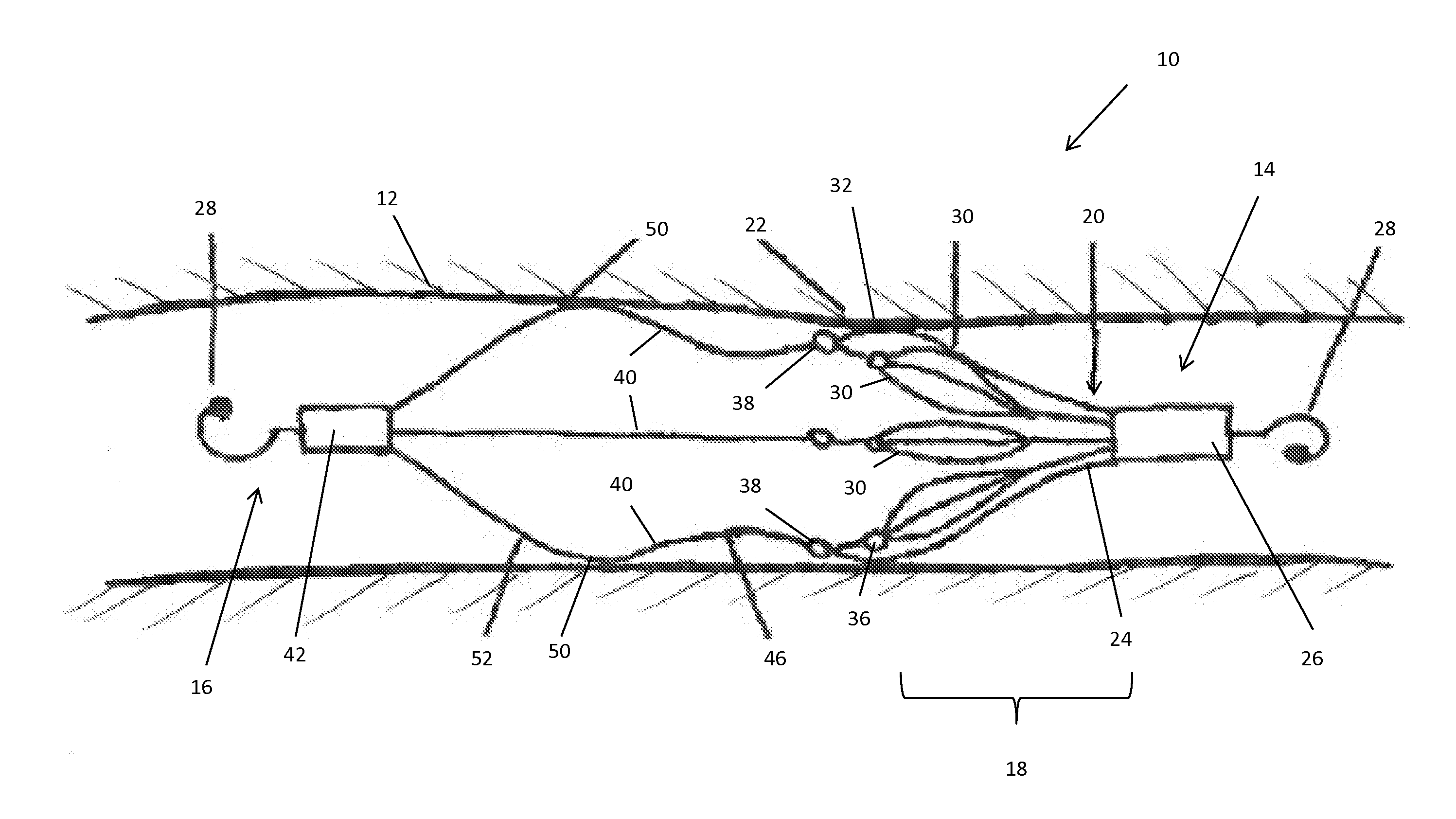
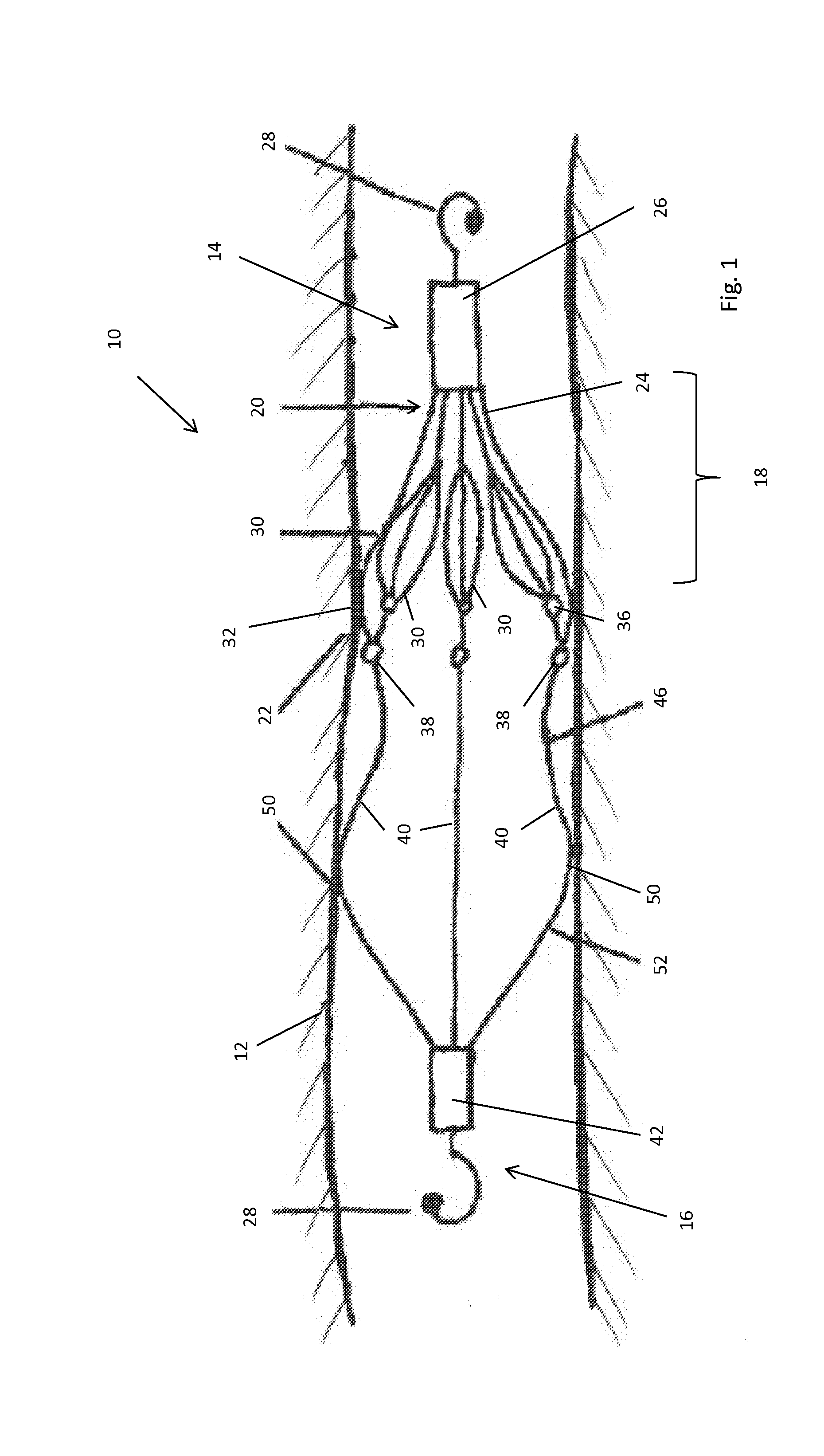
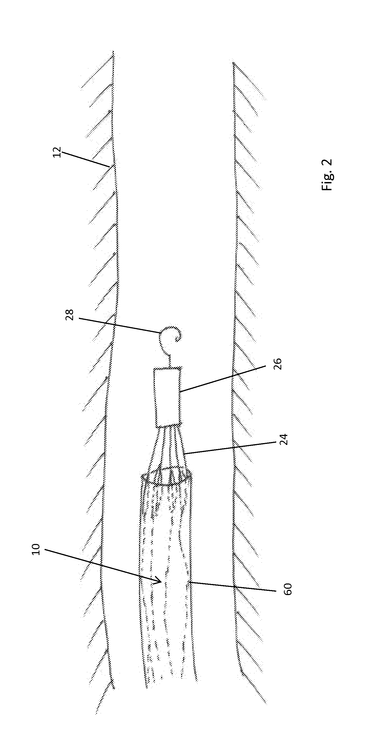
[0032]There is described below a preferred embodiment of the present invention, which is configured as a vena cava filter. It is to be understood though that the teachings herein are not limited to vena cava filters and are equally applicable to filters disposed in other body lumens and can also be modified to form an occlusion device or an embolic protection device.

[0033]Referring first to FIG. 1, this shows an embodiment of implantable medical device 10 deployed in the vena cava 12 of a patient. The medical device has a longitudinal dimension extending to first and second ends 14 and 16. The medical device 10 includes a material capture element 18 which has a generally closed conical deployed shape with a narrow end 20 disposed at or proximate the first end 14 of the device 10, and a wide end 22 facing the second end 16 of the device 10.

[0034]The material capture element 18 in this embodiment is configured as a filter and is formed of a plurality of wires 24 arranged in the form o...


PUM


Abstract

The disclosure provides an implantable medical device comprising a material capture element, which has a generally closed conical deployed shape and a narrow end disposed at or proximate the first end of the device. The material capture element includes a wide end facing the second end of the device, the material capture element having a zone of wider radial dimension which provides a first vessel contact site. A plurality of wire tethers are coupled to the wide end and extend to the second end. The wire tethers define a substantially open passageway for blood and provide a second vessel contact site. The first and second contact sites are spaced longitudinally from one another to provide stability. A first retrieval element is disposed at the first end and coupled to the narrow end, while a second retrieval element is disposed at the second end and coupled to the wire tethers.

Description

CROSS-REFERENCE TO RELATED APPLICATIONS[0001]This application claims the benefit of priority under 35 U.S.C. §119(a) to G.B. Patent Application Number 1316019.7, filed Sep. 9, 2013, which is incorporated by reference here in its entirety.TECHNICAL FIELD[0002]The present invention relates primarily to a vena cava filter although the structure of device taught herein can equally be used for an occlusion device. The skilled person will also appreciate that the device could be used in other parts of a patient's anatomy and not just in the vena cava.BACKGROUND ART[0003]Filters for placement in the vena cava are well known. A preferred filter shape is conical and sized such that the wide end of the cone is sufficiently large to be able to abut and press against the vessel wall, often fixed thereto by barbs or similar anchoring devices. The narrow end of the filter is typically closed. The filter is often formed as a mesh of wires or struts having apertures which are sufficiently large to ...

Claims


Application Information

Patent Timeline
IPC IPC(8): A61F2/01A61B17/12
CPCA61F2/01A61F2230/0006A61F2230/0093A61B17/12109A61F2002/016A61F2230/0078A61F2250/0039A61F2/0108A61F2230/001A61F2230/0067A61F2230/0095
Inventor ANDERSEN, TORBEN PETERKOLD, JENS
Owner COOK MEDICAL TECH LLC
Features
  • R&D
  • Intellectual Property
  • Life Sciences
  • Materials
  • Tech Scout
  • Unparalleled Data Quality
  • Higher Quality Content
  • 60% Fewer Hallucinations
Learn More