Toilet controls

Active Publication Date: 2015-03-19
AQUA MIZER
View PDF2 Cites 12 Cited by
  • Summary
  • Abstract
  • Description
  • Claims
  • Application Information

AI Technical Summary

Benefits of technology

[0006]The present invention relates to new and improved controls for use in association with a toilet. The controls enable water to be co

Problems solved by technology

If the outlet valve leaks, water will flow from the tank.
However, since the float engages the separate body of water in the container, the water inlet valve will

Method used


Image

  • Toilet controls
  • Toilet controls
  • Toilet controls

Examples


Embodiment Construction

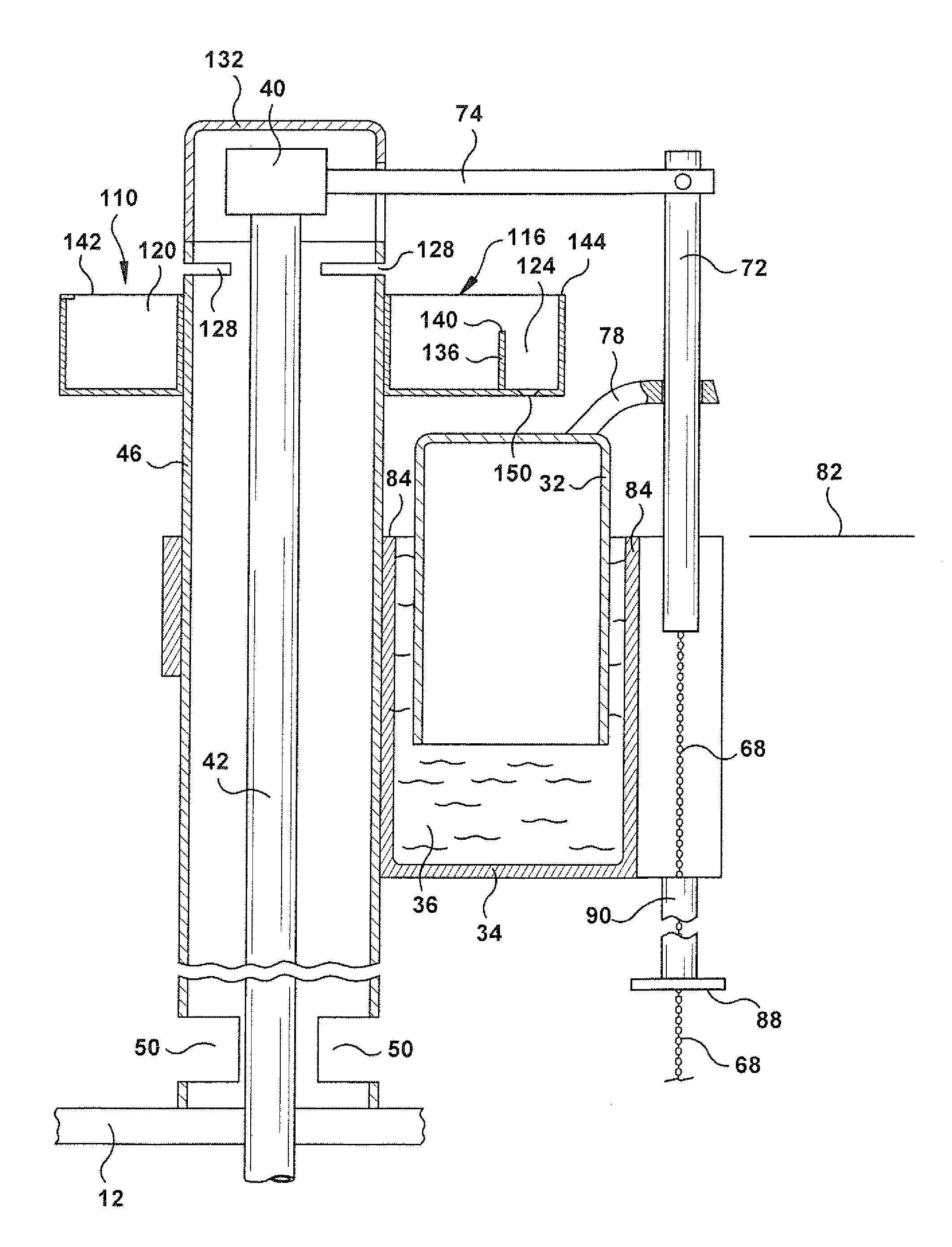
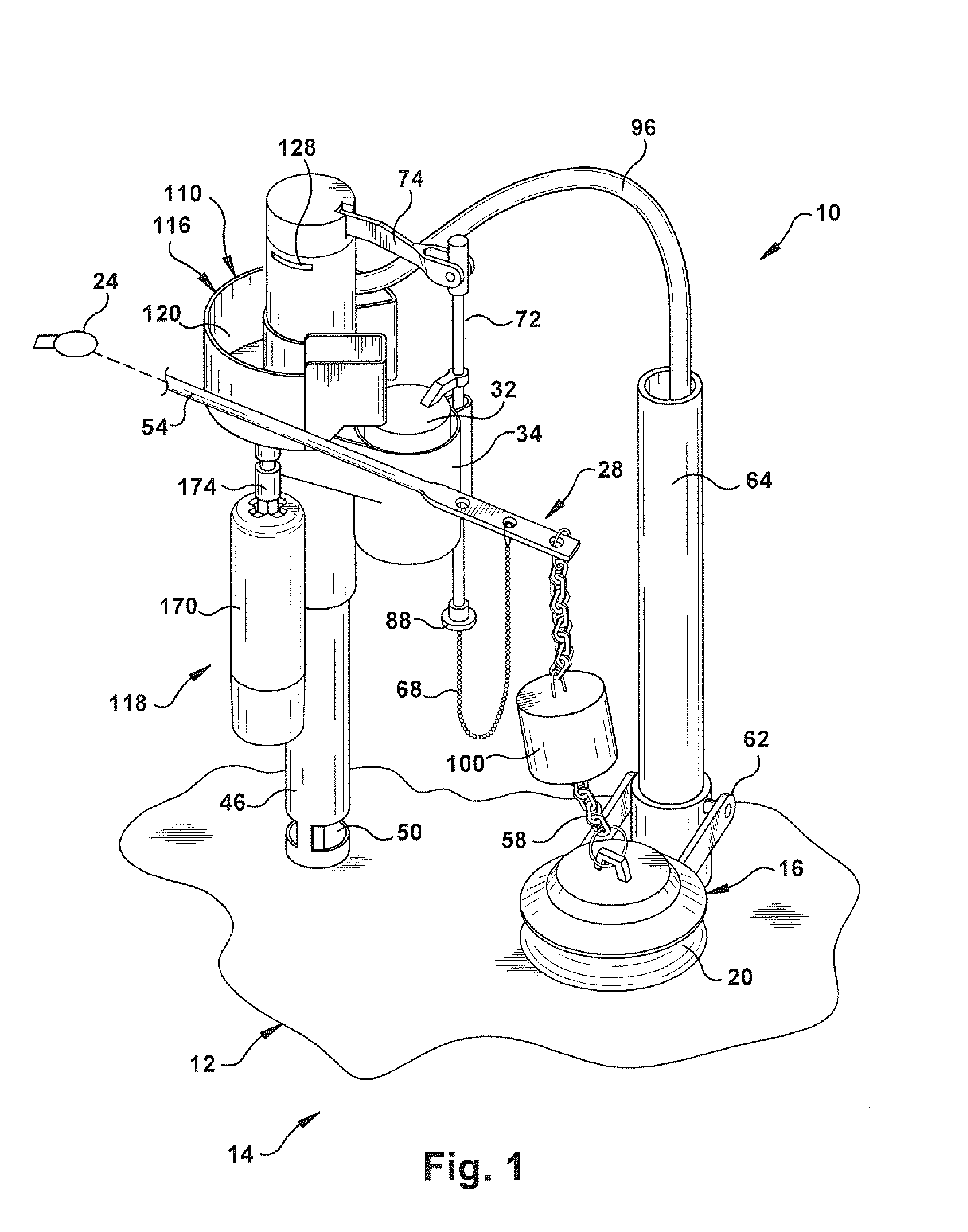
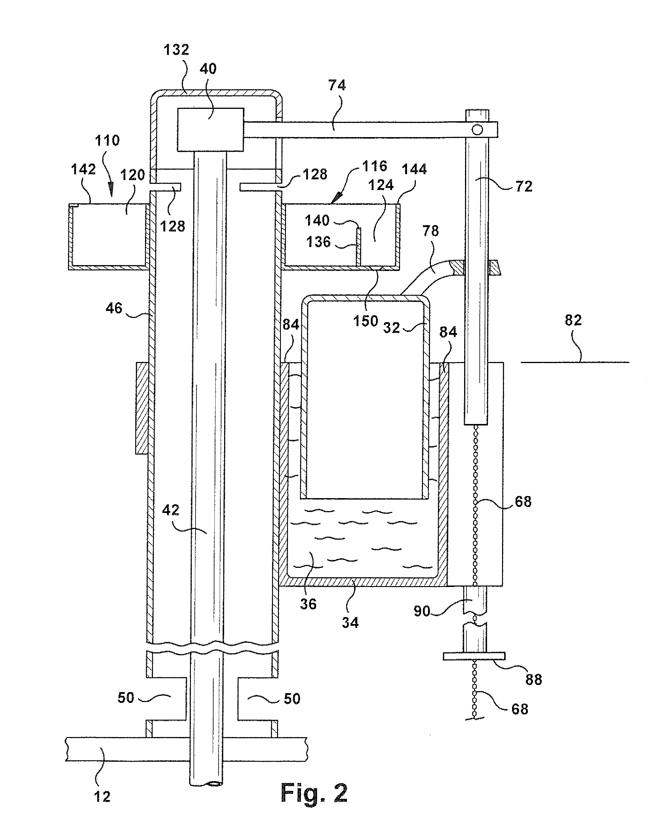
[0016]A toilet control apparatus 10, constructed in accordance with the present invention is illustrated in FIG. 1 in association with a main tank 12 of a toilet 14. The tank 12 is connected in fluid communication with a toilet bowl through an outlet valve 16. The outlet valve 16 is of the well known flapper type.

[0017]The outlet valve 16 is illustrated (FIG. 1) in a closed condition blocking the flow of water through an outlet opening 20. The toilet control apparatus 10 is operable, in response to manual actuation of a handle 24 mounted on the outside of the tank 12, to pivot the outlet valve 16 upwardly. This moves the outlet valve 16 from the closed condition of FIG. 1 to an open condition in which water flows from the main tank 12 through the outlet opening 20.

[0018]Upon manual actuation of the handle 24, a force transmitting assembly 28 transmits force from the handle 24 to the outlet valve 16 to pivot the outlet valve upwardly (as viewed in FIG. 1). This enables water to flow ...


PUM


Abstract

Controls for use in association with the main tank of a toilet include a container which is disposed in the main tank and holds a body of water. A float is movable in the container to expel water from the container and effect operation of an inlet valve from a closed condition to an open condition. Water flows into an inlet compartment and into the main tank when the inlet valve is in the open condition. Water flows into an outlet compartment after a predetermined quantity of water has accumulated in the inlet compartment. Water flows from the outlet compartment into the container.

Description

RELATED APPLICATIONS[0001]This application claims the benefit of the earlier filing date of U.S. Provisional Patent Application No. 61 / 873,072 filed Sep. 3, 2013. The disclosure in the aforementioned U.S. Provisional Patent Application No. 61 / 873,072 is hereby incorporated herein in its entirety by this reference thereto.BACKGROUND OF THE INVENTION[0002]The present invention relates to new and improved controls for use in association with a toilet.[0003]Known toilets include a tank which holds a supply of water. When a handle is manually depressed, water flows from the tank through an outlet or valve into a toilet bowl. The flow of water into the tank is controlled by a float actuated inlet valve.[0004]After a flow of water is conducted from the tank to a toilet bowl, the outlet valve is closed. This enables water to accumulate in the tank. If, for some unforeseen reason, the outlet valve remains or becomes stuck in an open condition or in a condition in which there is a substantial...

Claims


Application Information

Patent Timeline
IPC IPC(8): E03D1/33E03D1/32E03D1/34E03D5/092
CPCE03D1/33E03D1/34E03D1/32E03D5/092E03D1/00E03D1/308E03D1/36F16K33/00
Inventor KIM, JONATHAN S.
Owner AQUA MIZER
Why Eureka
Try Eureka