Vacuum sustaining heating systems and methods

a heating system and vacuum technology, applied in lighting and heating apparatus, heating types, steam separation arrangements, etc., can solve problems such as major maintenance, repair and replacement problems, condensate hammering, and increased maintenance costs due to additional vacuum equipmen

Active Publication Date: 2015-03-19
ZHADANOVSKY IGOR
View PDF18 Cites 15 Cited by
  • Summary
  • Abstract
  • Description
  • Claims
  • Application Information

AI Technical Summary

Benefits of technology

[0019]Another embodiment of the present invention is the system described above, wherein radiators on lowest floor(s) of high rise buildings are connected to separator via separate line in order to prevent condensate flooding from radiators at upper floors.
[0026]Another embodiment of the present invention is the system described above, further comprising means to prevent condensate hammering in return lines of vacuum heating system, wherein lines from radiators to a vertical collector line are smaller in diameter, and wherein the vertical collector is divided into compartments by soxhlet like separators.

Problems solved by technology

Although there are some efficiency gains, the conversion of a steam system into a vacuum system results in an increased maintenance cost due to additional vacuum equipment, condensate pumps, and electricity usage.
Malfunctioning steam trap deteriorates vacuum system performance, causes vacuum pump overload by hot vapor and is a major maintenance, repair, and replacement problem.
Few new vacuum systems have been installed in the last fifty years due to high installation and maintenance costs.
Existing steam (vapor) systems are robust and reliable but have multiple problems, including high installation costs, noise, uneven heat distribution, and control difficulties.
Therefore, many worn out steam systems are being retrofitted into hot water heating systems.
However, such retrofits are very expensive because the boiler and the old plumbing have to be replaced which requires significant demolition of building internals.

Method used


Image

  • Vacuum sustaining heating systems and methods
  • Vacuum sustaining heating systems and methods
  • Vacuum sustaining heating systems and methods

Examples


Embodiment Construction

[0060]The following description is merely exemplary in nature and is in no way intended to limit the present disclosure, application, or uses.

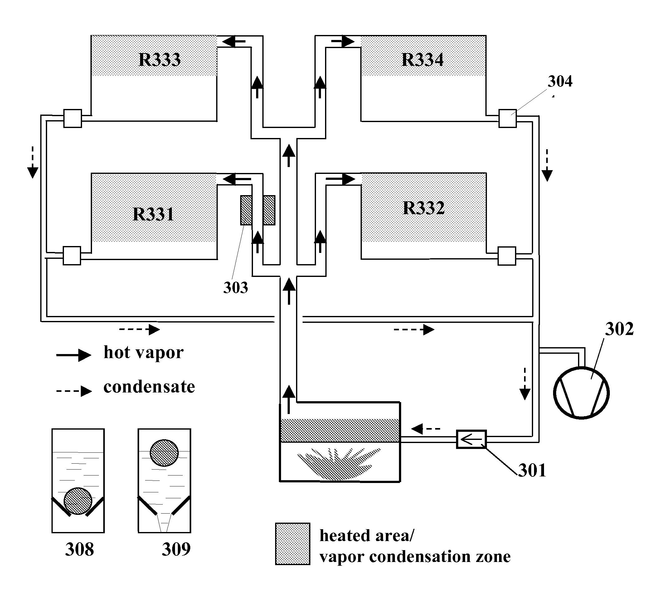
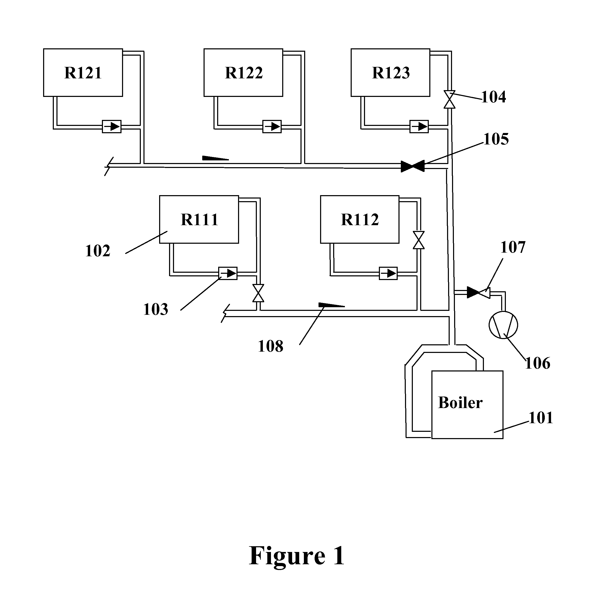
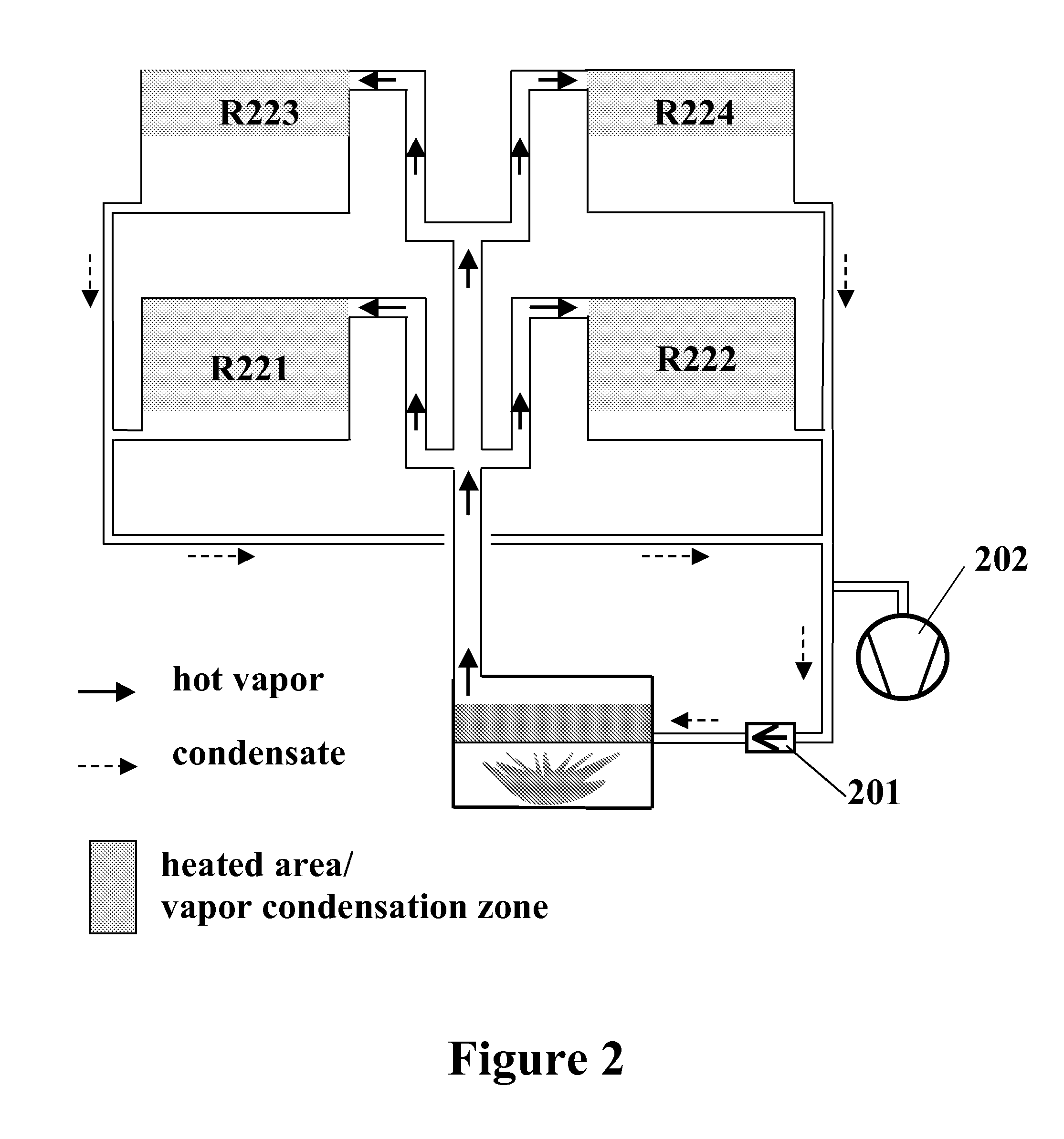
[0061]In order to solve the aforementioned problems with conventional steam, vacuum, and hot water heating systems, presented herein are numerous improvements to vapor vacuum systems, including:[0062](1) First is presented single-pipe vapor vacuum systems having a low temperature periodic condensate return.[0063](2) Second is presented an embodiment of a two-pipe vapor vacuum system without steam traps.[0064](3) Third is disclosed systems and methods for integrating the two-pipe vapor vacuum system with a condensing boiler.[0065](4) Fourth is presented several systems and method of operating radiators with the vapor vacuum system to ensure low temperature condensate return.[0066](5) Fifth are presented several designs for condensing vacuum boilers that can be utilized with the low temperature vapor vacuum system.[0067](6) Sixth is presented a ...


PUM


Abstract

In order to solve the numerous problems with existing steam, vacuum, and hot water heating systems, presented are novel systems and methods of vapor vacuum heating having several improvements over the prior art, including: condensate return which can operate without steam traps; naturally-induced vacuum; improved vacuum pump operation for sustaining vacuum in such systems; liquid lift apparatus for use with such systems; and other improvements. All innovations presented herein make vapor vacuum heating more efficient and economical for industrial, commercial, and home applications. A field test conducted with these innovations show results of about 26-50% reduced energy usage, implying significant energy savings from the use of the present invention over current heating systems.

Description

REFERENCES TO RELATED APPLICATIONS[0001]This application is a Non-Provisional application and claims the benefit of priority from a Provisional application U.S. Ser. No. 61 / 908,485, filed Nov. 25, 2013, entitled “Vacuum Sustaining Heating System,” the entirety of which is hereby incorporated by reference herein.[0002]Furthermore, this application is a Continuation-In-Part of non-provisional application U.S. Ser. No. 14 / 256,978, filed Apr. 20, 2014, entitled “Vapor Vacuum Condensing Boiler Designs,” which itself claims the benefit of priority from a non-provisional application U.S. Ser. No. 14 / 025,292, filed Sep. 12, 2013, entitled “Vapor vacuum heating systems and integration with condensing vacuum boilers,” issued as U.S. Pat. No. 8,702,013, which itself claims the benefit of priority from a provisional application U.S. Ser. No. 61 / 702,533, filed on Sep. 18, 2012, entitled “Condensing boiler and vapor vacuum heating system combo,” the entirety of all of which are hereby incorporate...

Claims


Application Information

Patent Timeline
Patent Type & Authority Applications(United States)
IPC IPC(8): F24D19/10F24D19/00F24D19/08F24D1/08
CPCF24D19/1003F24D19/081F24D19/0012F24D1/08Y02E20/14F01K17/02F22B35/005F24H1/0009F24D1/00F24D1/02F24D2220/0264F16T1/48Y02B30/00
Inventor ZHADANOVSKY, IGOR
Owner ZHADANOVSKY IGOR
Why Eureka
Try Eureka