Coupler for a rotatable cuttter assembly
Active Publication Date: 2015-03-19
KENNAMETAL INC
8 Cites 7 Cited by
AI-Extracted Technical Summary
Problems solved by technology
One problem associated with the drilling operation for drilling the bore hole into the roof of the mine is that a large amount of noise is generated.
Studies have shown that, on average, drilling noise is the most significant contributor to a roof bolting machine operator's noise exposure.
Another problem associated with the drilling operation for drilling...
Benefits of technology
[0009]These and other aspects of the invention will be more fully...
Abstract
A coupler for use in connecting together in a driving relationship a first member and a second member in a rotatable cutter assembly includes an elongate body having an axial forward end and an axial rearward end, and the elongate body containing a longitudinal bore. The elongate body further includes a collar mediate of the axial forward end and the axial rearward end, a forward body portion axially forward of the collar wherein the forward body portion is configured to drivingly engage the first member and a rearward body portion rearward of the collar wherein the rearward body portion is configured to drivingly engage the second member. The rearward body portion of the elongate body includes an elastomeric layer formed thereon.
Application Domain
Yielding couplingDrilling rods +4
Technology Topic
EngineeringMechanical engineering
Image
Examples
- Experimental program(1)
Example
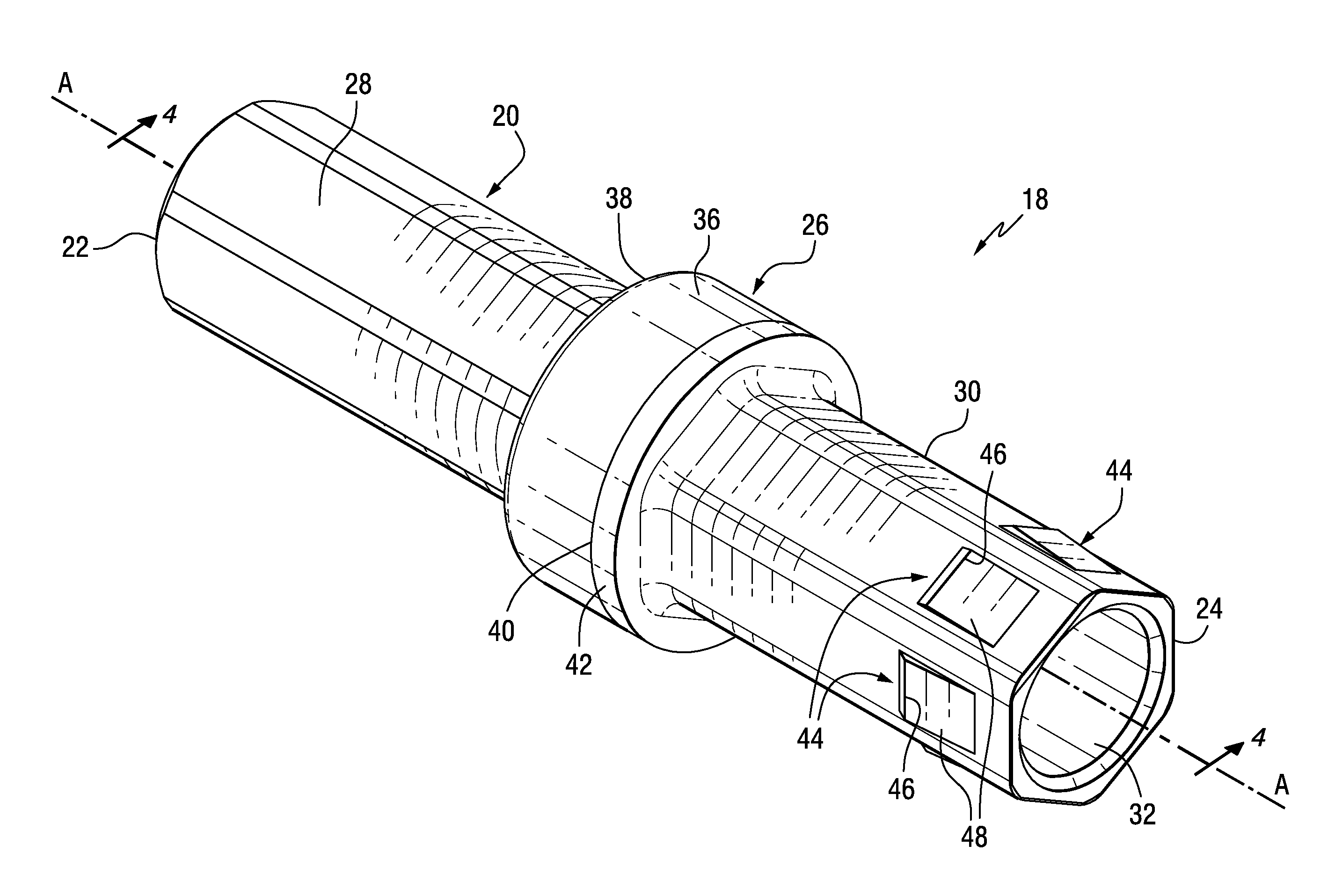
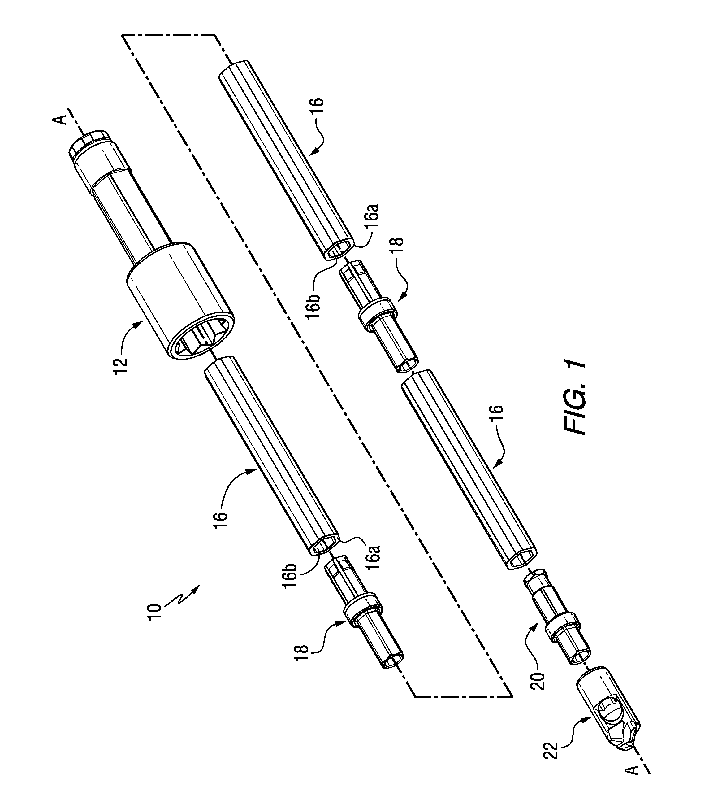
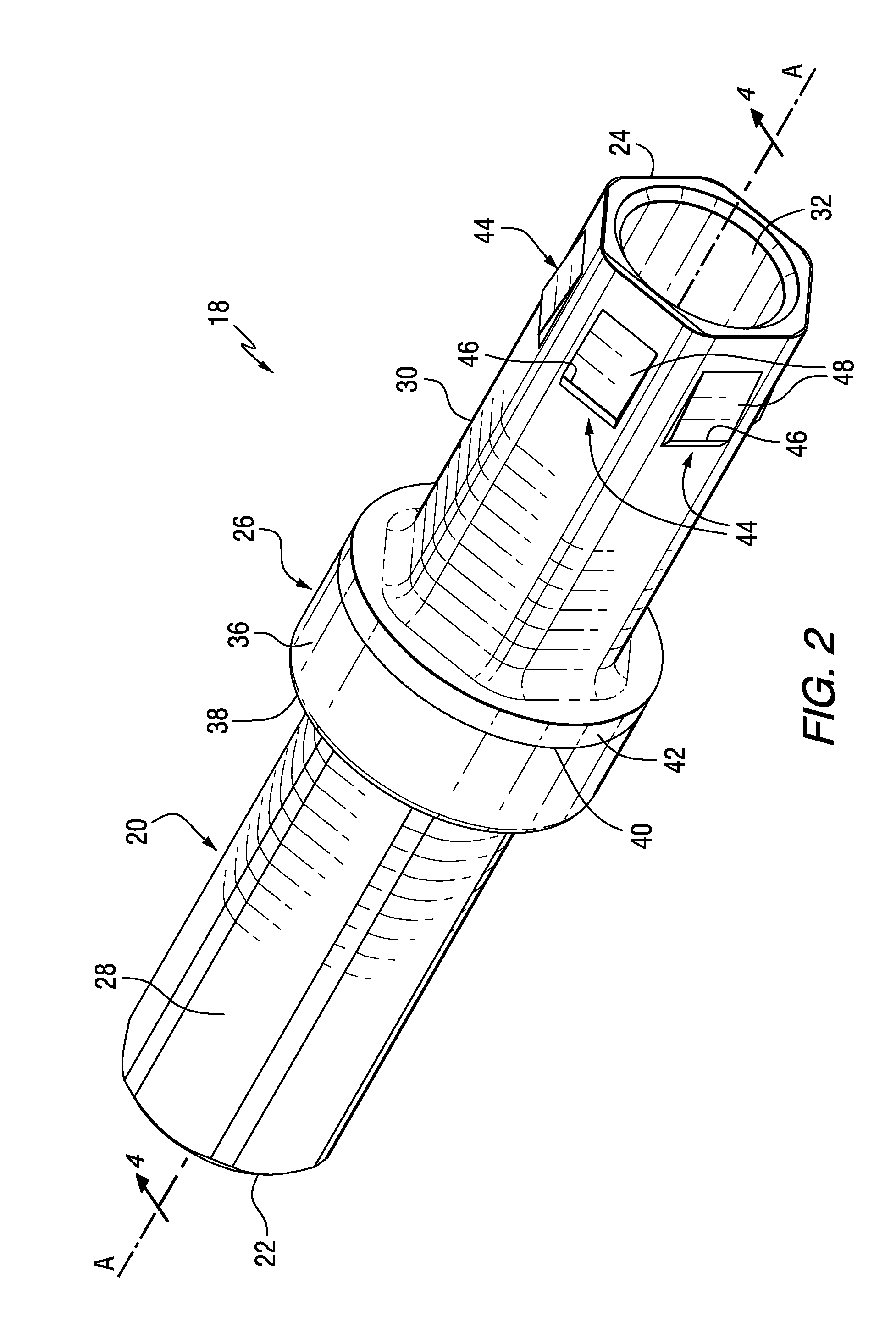
[0016]In accordance with an aspect of the invention, there is provided a coupler for a rotatable cutter assembly. The rotatable cutter assembly may be any such type of assembly, but for exemplary purposes only a rotatable cutter assembly in the form of a roof bolt drill assembly 10 (see FIG. 1) is described and illustrated herein. Thus, it will be appreciated that the invention is not limited to a roof bolt drill assembly.
[0017]As will be appreciated from the description and drawings set forth herein, the invention advantageously provides for reduced noise during a drilling operation, as well as, improved mechanical durability and flexibility of the roof bolt drill assembly during the drilling operation.
[0018]Referring to the drawings, FIG. 1 illustrates the rotatable cutter assembly (e.g. a roof drill bit assembly 10) of the invention. The roof drill bit assembly 10 includes a chuck adapter (or chuck) generally designated as 12, one or more sections of drill steels each one of which is generally designated as 16, one or more couplers generally designated as 18 for attaching or connecting together in a driving relationship one or more members such as drill steels 16, and an adapter generally designated as 20 for attaching or connecting a roof drill bit generally designated as 22. The components of the roof drill bit assembly 10 are exploded along a common longitudinal axis A-A for sake of clarity. However, it should be appreciated that for the purpose of operation, these components would be assembled together to form an assembled roof drill bit assembly. The roof drill bit assembly 10 would also typically include a means for driving the assembly 10 which may be, for example, a drill or drilling machine, (not shown).
[0019]Referring to FIGS. 2-6, the coupler 18 is illustrated in more detail, in accordance with aspects of the invention. Specifically, the coupler 18 includes an elongate body 20 having an axial forward end 22 and an axial rearward end 24, a collar 26 that is generally central to or mediate of the axial forward end 22 and the axial rearward end 24. The coupler 18 further includes a forward body portion 28 axially forward of the collar 26 wherein the forward body portion 28 is configured to drivingly engage a first member such as, for example, one of the drill steels 16. The coupler 18 also includes and a rearward body portion 30 rearward of the collar 26 wherein the rearward body portion 30 is configured to drivingly engage a second member such as, for example, one of the drill steels 16. The elongate body 20 of the coupler 18 also may include a longitudinal bore 32 extending therethrough for delivering air/vacuum, water or coolant depending upon the desired type drilling operation desired.
[0020]In accordance with an aspect of the invention, the rearward body portion 30 of the elongate body 20 includes a first elastomeric layer 34 formed thereon. In one particular aspect, the elastomeric layer 34 can extend from adjacent the collar 26 to the axial rearward end 24 of the elongate body 20 so as to cover the generally the entire outer periphery of the rearward body portion 30.
[0021]In accordance with another aspect of the invention, the collar 26 includes a flange 36 extending radially outward from the elongate body 20, wherein the flange 36 includes a forward surface 38 adjacent the forward body portion 28 and a rearward surface 40 adjacent the rearward body portion 30. In one aspect, the rearward surface 40 of the flange 36 includes a second elastomeric layer 42 formed thereon. In another aspect, the second elastomeric layer 42 is contiguous with the first elastomeric layer 34, e.g. the first elastomeric layer 34 and the second elastomeric layer 42 are in contact and form a continuous or uninterrupted elastomeric surface.
[0022]When the roof drill bit assembly 10 is assembled, the rearward body portion 30 of the coupler 18 is inserted in one of the drill steels 16 such that a first end 16a of the drill steel 16 engages or contacts the second elastomeric layer 42 formed on the rearward surface 40 of the flange 36. In addition, an inner surface 16b of the drill steels 16 is configured to engage or contact similarly configured first elastomeric layer 34 formed on the rearward body portion 30 in, for example, a press fit arrangement so as to provide a driving engagement relationship therebetween. Typically, the drill steels 16 are formed of a hard, rigid material such as, for example, steel. However, the elastomeric layers 34, 42 are formed of a material that is generally less hard or less rigid in comparison to the material used to form the drill steels 16 (or other components that coupler 18 may be used in association with as well). For example, elastomeric layers 34, 42 can be constructed from polyisoprene, a polyisoprene blend, butyl rubber, acryl rubber, polyurethane, flurorubber, polysulfide rubber, ethylene-propylene rubber (EPR and EPDM), Hypalon, chlorinated polyethylene, ethylene-vinyl acetate rubber, epichlorohydrin rubber, chloroprene rubber, silicone, or other heavily damped elastomer. Accordingly, it will be appreciated that the elastomeric layers 34, 42 are advantageously configured so as to reduce, suppress and/or dampen the sounds, noises and/or vibrations generated by the assembly 10 during operation. If the coupler 18 were constructed without the elastomeric layers 34, 42 and otherwise constructed of a hard, rigid material the same as or similar to the drill steel 16 material, there would be a large amount of sounds, noises and/or vibrations generated by the assembly 10 during operation. Such sounds, noises and/or vibrations generated by the assembly 10 during operation are generally undesirable, particularly in an underground mining environment. As used herein, “layer” or “elastomeric” or “elastomeric layer” or like phrases can include one or more layers of elastomeric material for tuning or adjusting noise reduction or suppression.
[0023]As shown in FIG. 5, the first elastomeric layer 34 formed on the rearward body portion 30 has a first thickness T1 that is less than a second thickness T2 of the second elastomeric layer 42 formed on the rearward surface 40 of the flange 36. The second elastomeric layer 42 is thicker due to the nature of the contact and interaction between the end 16a of the drill steel 16 therewith as described.
[0024]In accordance with another aspect of the invention, the rearward body portion 30 of the elongate body 20 includes an elastomeric retainer element 44 formed thereon and configured to engage a driving member, e.g. one of the drill steels 16 or other components. In one aspect, the rearward body portion 30 of the elongate body 20 includes a plurality of elastomeric retainer elements 44 formed about an outer periphery thereof.
[0025]The elastomeric retainer element 44 includes a raised projection 46 extending radially outward from the elongate body 20. The elastomeric retainer element 44 further includes a bearing surface 48 that slopes axially inwardly from the raised projection 46 toward the axial rearward end 24 of the elongate body 20. Advantageously, the elastomeric retainer element 44 is configured to facilitate the coupler 18 being inserted into the drill steel 16 while also resisting the coupler 18 and the drill steel 16 from becoming disconnected. Specifically, the bearing surface 48 is sloped as described to allow for the end 16a and inner surface 16b of the drill steel to pass over the elastomeric retainer element 44 when connecting the coupler 18 and the drill steel 16. Once assembled, the inner surface 16b of the drill steel 16 engages the raised projection 46 to provide a press fit or interference fit therebetween that provides resistance to the coupler 18 and the drill steel 16 from becoming disconnected or separated during use of the drill assembly 10.
[0026]In another aspect of the invention, the rearward body portion 30 of the elongate body 20 includes a recess 50 formed therein for receiving an inner portion 52 of the elastomeric retainer element 44. This configuration aids in maintaining the elastomeric retainer element 44 in position and secured to the rearward body portion 30.
[0027]In another aspect, the elastomeric retainer element 44 is contiguous with the first elastomeric layer 34, e.g. the first elastomeric layer 34 and the elastomeric retainer element 44 are in contact and form a continuous or uninterrupted elastomeric surface that covers the rearward body portion 30.
[0028]Advantageously, configuring the coupler 18 and, in particular, the first elastomeric layer 34, the second elastomeric layer 42 and/or the elastomeric retainer element 44 of the coupler 18 as described and illustrated herein, provides for the coupler 18 to act as a sound dampening apparatus capable of providing absorption and dissipation of the energy during a drilling operation so as to minimize or reduce the noise, sound and/or vibration that occurs during a drilling operation and, in particular, during a roof bolt drilling operation.
[0029]In addition to the coupler 18 of the invention acting as a sound dampening apparatus capable of providing absorption and dissipation of the energy during a drilling operation so as to minimize or reduce the noise, sound and/or vibration that occurs during a drilling operation, the coupler 18 of the invention also advantageously reduces the potential for mechanical failure of the roof bolt drill assembly 10 during operation. Specifically, the coupler 18 by having the first elastomeric layer 34, the second elastomeric layer 42 and/or the elastomeric retainer element 44 provides for reduced or decreased wear between the coupler 18 and the drill steel 16 as well as increases the overall life of other components of the assembly 10 due to, fore example, reduced vibrational wear. The coupler 18 of the invention allows for the stiffness or rigidity of the assembly 10 to be controlled or adjusted as desired to reduce or minimize mechanical failure of the various components that make up the assembly 10. For example, previously known roof bolt drill assemblies would have a stiff or rigid mechanical connection between couplers and drill steels. During operation, these components experienced large mechanical stresses and/or forces due to the nature of the roof bolt drilling process. Thus, it will be appreciated that the coupler 18 of the present invention advantageously reduces the mechanical stresses and/or forces that the drill assembly components are subjected to as a result of the coupler 18 having the first elastomeric layer 34, the second elastomeric layer 42 and/or the elastomeric retainer element 44.
[0030]Whereas particular embodiments of this invention have been described above for purposes of illustration, it will be evident to those skilled in the art that numerous variations of the details of the present invention may be made without departing from the invention as defined in the appended claims.
PUM


Description & Claims & Application Information
We can also present the details of the Description, Claims and Application information to help users get a comprehensive understanding of the technical details of the patent, such as background art, summary of invention, brief description of drawings, description of embodiments, and other original content. On the other hand, users can also determine the specific scope of protection of the technology through the list of claims; as well as understand the changes in the life cycle of the technology with the presentation of the patent timeline. Login to view more.