AI technical title is built by Patsnap AI team. It summarizes the technical point description of the patent document.
a technology of switches and switches, applied in the field of switches, can solve the problems of increasing the number of contacts that perform interrupting/conducting operations, causing loss, and causing a large load on the operation par
Inactive Publication Date: 2015-03-26
KK TOSHIBA
View PDF0 Cites 8 Cited by
Summary
Abstract
Description
Claims
Application Information
AI Technical Summary
This helps you quickly interpret patents by identifying the three key elements:
Problems solved by technology
Method used
Benefits of technology
Benefits of technology
The gas switch described in this patent aims to be a high-voltage switch that is easy to use and has a fast interruption time.
Problems solved by technology
A cause of a great load to the operation part is not only an increase of the number of the contacts which perform the interrupting / conducting operations but also a loss due to structures for transmitting a driving force of the single operation part to the plural contacts.
Therefore, a large driving force is necessary, and the kind and size of the operation part are limited.
When operation energy cannot be made large, there is a disadvantage that the interruption time becomes long.
Method used
Image
Click on the blue label to locate the original text in one second.
Reading with bidirectional positioning of images and text.
Examples
first embodiment
Whole Structure
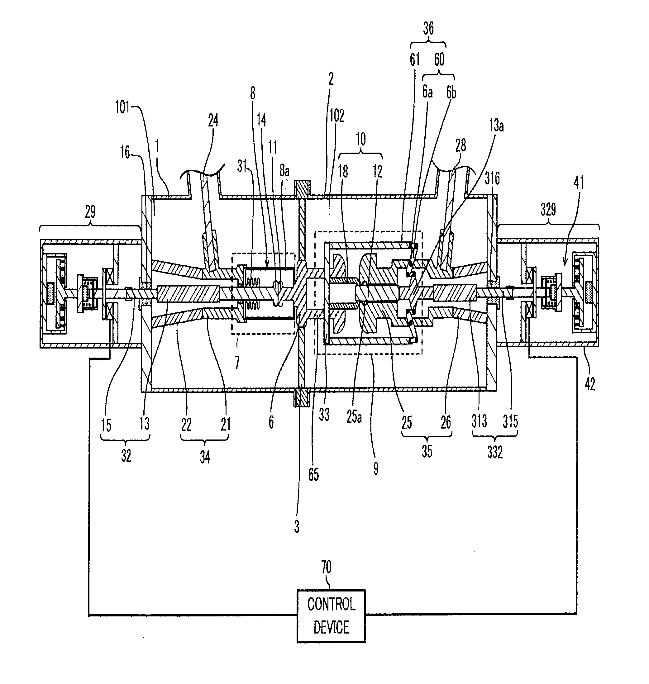
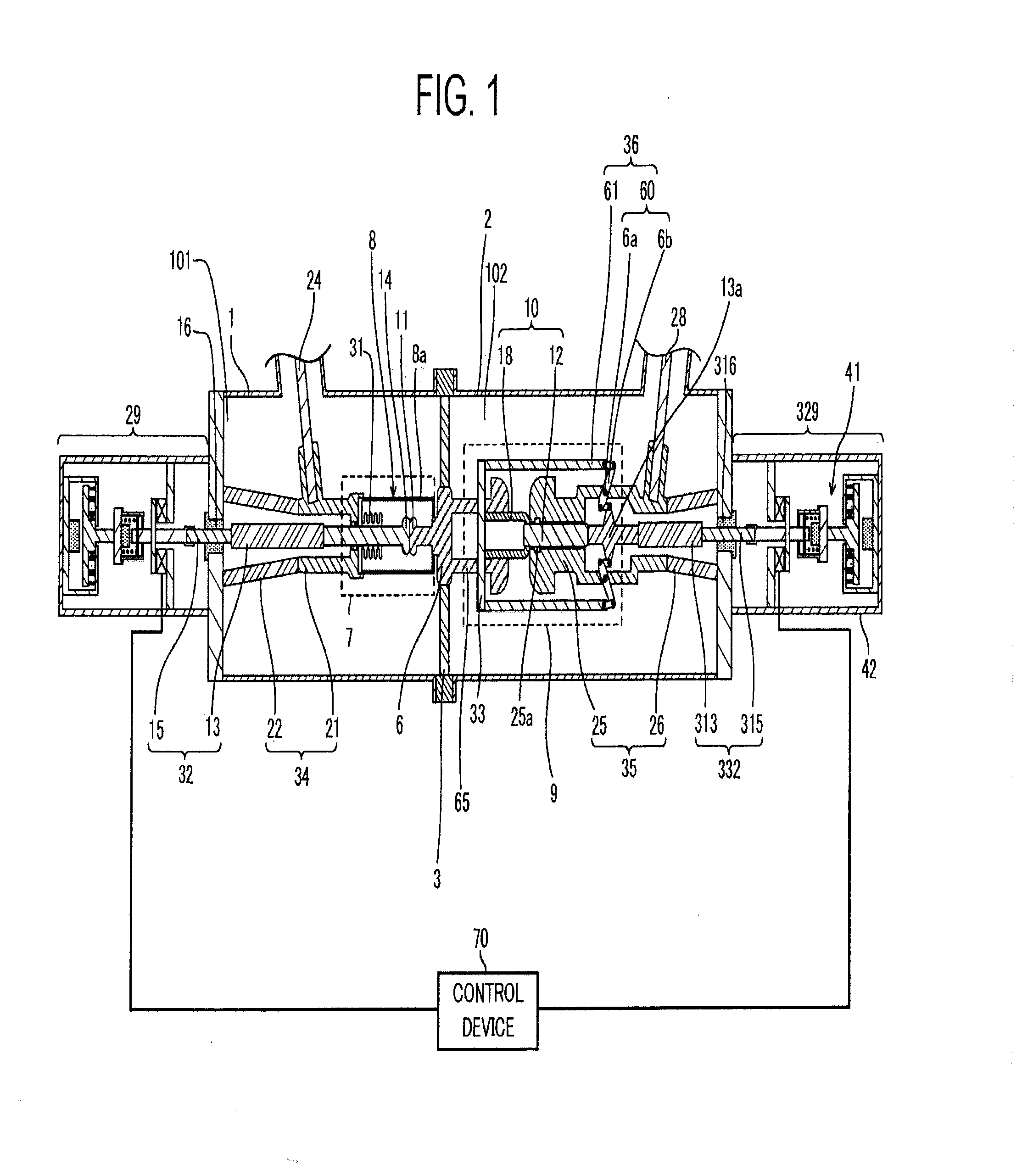
[0026]Hereinafter, the structure of a switch of this embodiment will be described with reference to FIG. 1 to FIG. 3.
[0027]FIG. 1 and FIG. 2 are cross-sectional views illustrating the structure of a gas circuit breaker of this embodiment.
[0028]Note that FIG. 1 illustrates a state where the switch is in a current conduction state, and FIG. 3 illustrates a state where the switch is in a current interruption state.
[0029]The switch of this embodiment has a plurality of contacts electrically connected in series, and switches over between the current conduction state and the current interruption state by connecting / separating the contacts.
[0030]The switch of this embodiment includes: pressure vessels 1, 2 made of grounded metal, insulator, or the like; a plurality of (two here) contact parts 7, 9 having a pair of contacts that are connectable / separable; an insulating spacer 3 dividing the inside of the pressure vessels 1, 2 into the same number of (two here) spaces as the n...
second embodiment
Structure
[0177]A second embodiment will be described with reference to FIG. 4 and FIG. 5.
[0178]FIG. 4 and FIG. 5 are cross-sectional views of an electromagnetic repulsion operation part 41 as an example of an inner structure of an operation part 329 according to the second embodiment.
[0179]FIG. 4 illustrates a state of the electromagnetic repulsion operation part 41 when it closes a contact part (current conduction state).
[0180]FIG. 5 illustrates a state of the electromagnetic repulsion operation part 41 when it opens the contact part (state where a current is interrupted).
[0181]A basic structure of the second embodiment is the same as that of the first embodiment.
[0182]Only what are different from the first embodiment will be described, and the same parts as those of the first embodiment will be denoted by the same reference signs, and detailed description thereof will be omitted.
[0183]Here, the electromagnetic repulsion operation part 41 as an example of the inner structure of the...
PUM
Abstract
A switch includes: a second conductor; a second movable electrode provided in a second hermetic space so as to be movable in a first direction in which it parts from the fixed electrode and in a second direction opposite the first direction; an opposed electrode slidably provided in the fixed electrode to face the second movable electrode so as to open from and be in contact with the second movable electrode in an open state and a closed state respectively; a second driver which generates a driving force and moves the second movable electrode in the first direction when performing an opening operation; and a driving force transmitting mechanism which moves the opposed electrode in the second direction by converting a direction of the driving force for moving the second direction opposite the moving direction of the second movable electrode when the second driver generates the driving force for moving the second movable electrode in the first direction.
Description
CROSSREFERENCE TO RELATED APPLICATIONS[0001]This application is based upon and claims the benefit of priority from the prior Japanese Patent Application No. 2013-195042, filed on Sep. 20, 2013; the entire contents of which are incorporated herein by reference.FIELD[0002]Embodiments described herein relate generally to a switch.BACKGROUND[0003]A switch for high voltage responsible for interrupting a fault current has to satisfy the following two items when interrupting the current.[0004]One is to surely extinguish, in a very short time, an arc generated between contacts after the opening. The other is to prevent dielectric breakdown when a transient recovery voltage rapidly rises between the contacts after the arc extinction.[0005]In recent years, there has been widely adopted a puffer switch of a type in which one circuit breaker part having connectable / separable contacts are housed in a pressure vessel in which SF6 gas as insulating gas is sealed, and the insulating gas is sprayed ...
Claims
Application Information
Patent Timeline
Application Date:The date an application was filed.
Publication Date:The date a patent or application was officially published.
First Publication Date:The earliest publication date of a patent with the same application number.
Issue Date:Publication date of the patent grant document.
PCT Entry Date:The Entry date of PCT National Phase.
Estimated Expiry Date:The statutory expiry date of a patent right according to the Patent Law, and it is the longest term of protection that the patent right can achieve without the termination of the patent right due to other reasons(Term extension factor has been taken into account ).
Invalid Date:Actual expiry date is based on effective date or publication date of legal transaction data of invalid patent.
Patent Type & AuthorityApplications(United States)

