Transfer device, control device, transfer method, and multifunction peripheral

a control device and peripheral technology, applied in the direction of digital output to print units, visual presentations, instruments, etc., can solve the problems of large bandwidth load acting on the bus in copy processing, inability to perform copy processing correctly, and delay in data transfer for printing on the printer side, so as to achieve the effect of effectively using a bus and a processing circui

Active Publication Date: 2020-02-18
CANON KK
View PDF7 Cites 0 Cited by
  • Summary
  • Abstract
  • Description
  • Claims
  • Application Information

AI Technical Summary

Benefits of technology

[0005]An aspect of the present invention provides a configuration in which, when multiple processes are performed in parallel, a bandwidth necessary for performing each process can be assigned while also effectively using a bus and a processing circuit by simple control.
[0007]A transfer device that is one of a plurality of transfer devices each configured to transfer data between a storage device and a processing device, the storage device and the transfer devices being connected via a bus, and the transfer device comprising: an issuing unit configured to issue a request for transferring data via the bus; an analysis unit configured to analyze data to be transferred; and a switching unit configured to switch a state of a series of requests issued by the issuing unit between a first state and a second state in which a request from another transfer device interrupts more easily than in the first state, according to a data attribute obtained as a result of analysis.
[0008]According to the exemplary aspect of the present invention, when multiple processes are performed in parallel, a bandwidth necessary for performing each process can be assigned while also effectively using a bus and a processing circuit by simple control.

Problems solved by technology

However, the transfer of the image data obtained by the scanner and the image data used for printing is performed via a common bus, and therefore the bandwidth load acting on the bus becomes large in copy processing in which the scanner and the printer operate at the same time.
Particularly, if bus access from the scanner side temporarily becomes intensive during copy processing, the data transfer for printing is delayed on the printer side.
If the bus bandwidth necessary for the scan operation cannot be ensured, there is a possibility that copy processing will not be performed correctly due to a failure of obtaining data.
If data supply is delayed, a print head is no longer able to be operated continuously without stopping, and thus there is a possibility that printing will not be performed correctly.
However, in the method described in Japanese Patent Laid-Open No. 2014-107585, unless data to be transferred has always been prepared in the period in which using the bus is allowed, time for which the bus bandwidth cannot be used sufficiently will arise.
In the method described in Japanese Patent Laid-Open No. 2010-15275, it is difficult to predict the timing at which data transfer speed is suppressed, and therefore it is difficult to apply the method to a device for which real-time operations such as scan processing and print processing are needed.
However, this system is configured such that the wait cycle is switched by an event signal from a CPU, and therefore time is required to switch the data transfer speed, and stand-by time is required before moving to the next processing.
However, DMA transfer is performed in a divided manner also in the transfer of print processing setting values and in the transfer of scan processing setting values that need high-speed data transfer, and therefore the transfer speed is suppressed at an undesired timing.

Method used


Image

  • Transfer device, control device, transfer method, and multifunction peripheral
  • Transfer device, control device, transfer method, and multifunction peripheral
  • Transfer device, control device, transfer method, and multifunction peripheral

Examples


first embodiment

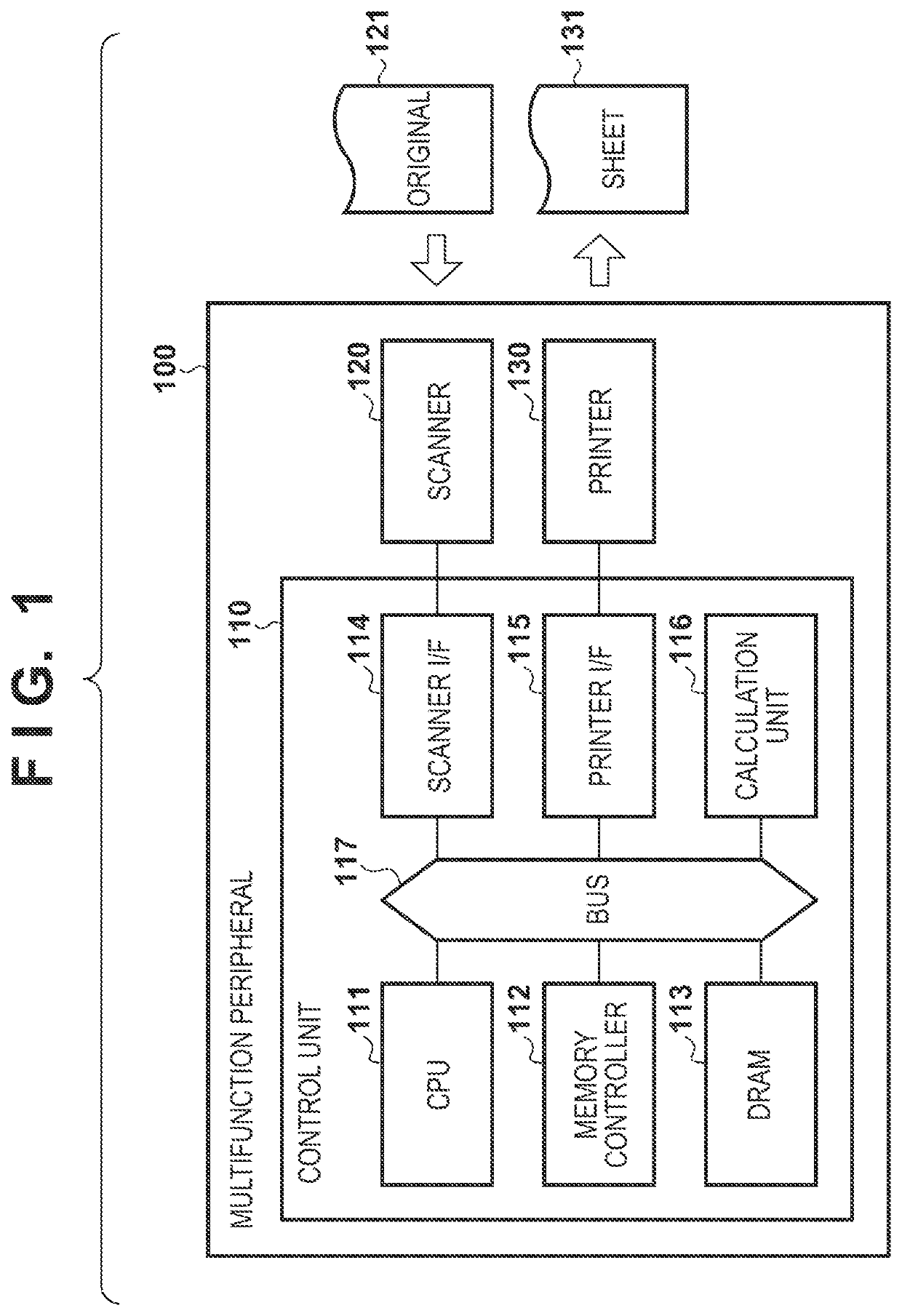
[0026]FIG. 1 is a block diagram showing an example of a configuration of a multifunction peripheral 100 according to a first embodiment. The multifunction peripheral 100 is provided with a control unit 110, a scanner 120, and a printer 130. The scanner 120 is an optical device by which an original 121 is read and converted to image data. Specifically, the scanner 120 emits light onto the original 121, receives a reflection light by an imaging element, generates analog data, performs A / D conversion, and thus obtains image data. The printer 130 is a printing device that discharges ink onto a sheet 131 according to print image data, and thus forms an image on the sheet 131. Note that, the printer 130 is not limited to such an inkjet-type printing device, and may be a printing device using an electrophotographic method or other printing method.

[0027]The control unit 110 is a control device that gives operation instructions to the scanner 120 and the printer 130 and performs image transf...

second embodiment

[0078]The main object of a second embodiment is to suppress power that is consumed in the calculation unit when data transfer is not performed. FIG. 10 is a block diagram showing the functions and configuration of a first input-side transfer unit 612 according to the second embodiment. In this embodiment, a clock control unit 608 is provided in the first input-side transfer unit 612. The same is true of the first output-side transfer unit, the second input-side transfer unit, and the second output-side transfer unit as well.

[0079]The clock control unit 608 is a control circuit that switches ON / OFF of a clock supplied to the scan image processing unit 214 according to a clock control signal transmitted from a synchronization control unit 604.

[0080]The synchronization control unit 604 issues a clock control signal to the clock control unit 608 according to the transfer sequence of data transfer. In the suppressed-speed transfer mode, the synchronization control unit 604 controls the c...

third embodiment

[0082]The main object of a third embodiment is to make it possible to control the data amount of a DMA transfer request according to the data attribute, and to assign bandwidth to a DMA transfer with high priority at an appropriate timing, while using the bandwidth of the bus 117 effectively. FIG. 11 is a block diagram showing the functions and configuration of a first input-side transfer unit 712 according to the third embodiment. In this embodiment, a DMA division unit 709 is provided in the first input-side transfer unit 712. The same is true of the first output-side transfer unit, the second input-side transfer unit, and the second output-side transfer unit.

[0083]The DMA division unit 709 is a control circuit that switches the number of divisions used when a DMA transfer request from the DMA transfer unit 301 is divided according to the transfer sequence of the synchronization control unit 704.

[0084]FIG. 12 is a flowchart for illustrating the division control in the DMA division...


PUM


Abstract

A transfer device is one of a plurality of transfer devices each configured to transfer data between a storage device and a processing device. The storage device and the transfer devices are connected via a bus. The transfer device comprise: an issuing unit configured to issue a request for transferring data via the bus; an analysis unit configured to analyze data to be transferred; and a switching unit configured to switch a state of a series of requests issued by the issuing unit between a first state and a second state in which a request from another transfer device interrupts more easily than in the first state, according to a data attribute obtained as a result of analysis.

Description

BACKGROUND OF THE INVENTIONField of the Invention[0001]The present invention relates to a transfer device, a control device, a transfer method, and a multifunction peripheral.Description of the Related Art[0002]In an apparatus having a scanning function and a printing function such as a multifunction peripheral, when copy processing is performed, while an original is read by a scanner, printing is performed at the same time in order to complete the processing quickly. At this time, processing is repeated in which image data obtained by scanning is successively stored in a DRAM via a bus, and in a stage when scanning of several lines is complete, the image data stored in the DRAM is read out and printing is executed. However, the transfer of the image data obtained by the scanner and the image data used for printing is performed via a common bus, and therefore the bandwidth load acting on the bus becomes large in copy processing in which the scanner and the printer operate at the sam...

Claims


Application Information

Patent Timeline
Patent Type & Authority Patents(United States)
IPC IPC(8): G06F13/42G06F3/12G06K15/02H04N1/00
CPCH04N1/00095G06F13/42G06F3/1293G06F13/4243G06K15/1817G06F3/124G06F3/1263G06F3/1279H04N1/00915H04N1/00954G06F13/12H04N2201/0081H04N2201/0084H04N2201/0091H04N2201/0094
Inventor KAWAMOTO, TOMOYUKIITO, TADAYUKI
Owner CANON KK
Why Eureka
Try Eureka