Rechargeable battery having an extendable case region

a rechargeable battery and extendable case technology, applied in the field of rechargeable batteries, can solve the problems of difficult view, radically deteriorating battery life, etc., and achieve the effects of reducing contact resistance, easy interrupting current, and easy dissipation of hea

Active Publication Date: 2014-04-15
ROBERT BOSCH GMBH +1
View PDF25 Cites 0 Cited by
  • Summary
  • Abstract
  • Description
  • Claims
  • Application Information

AI Technical Summary

Benefits of technology

[0012]An aspect of an embodiment of the present invention is directed toward a prismatic rechargeable battery having advantages of preventing overcharging.
[0043]With an embodiment of the present invention, a variable region is formed such that it can be elongated pursuant to the elevation in internal pressure, thereby easily interrupting the current when the internal pressure is increased.
[0044]Furthermore, when the variable region has concave and convex portions, the heat can be easily dissipated owing to the enlarged inner and outer surface area. In addition, when the uncoated region is directly welded to the case, the contact resistance can be reduced.

Problems solved by technology

With the conventional prismatic rechargeable battery, when overcharging continuously occurs, the battery may explode due to a radical elevation in voltage, or the lifespan of the battery may be radically deteriorated.
Although the electric current of the prismatic battery should be interrupted when overcharging occurs, it is not easy in view of the structural characteristics of the prismatic battery to employ a device for stably interrupting the electric current, unlike in a cylindrical battery.

Method used


Image

  • Rechargeable battery having an extendable case region
  • Rechargeable battery having an extendable case region
  • Rechargeable battery having an extendable case region

Examples


first embodiment

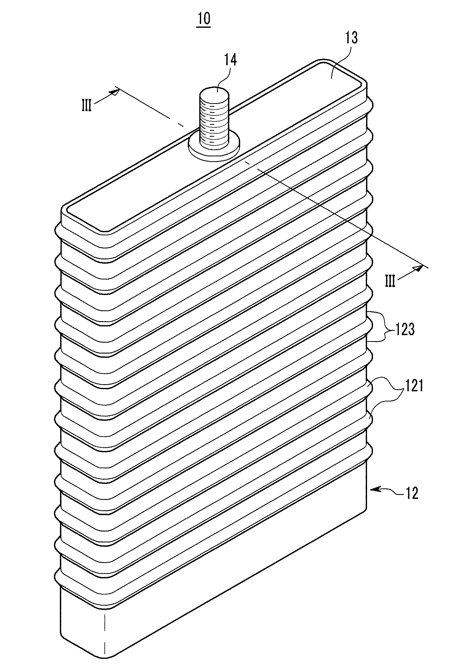
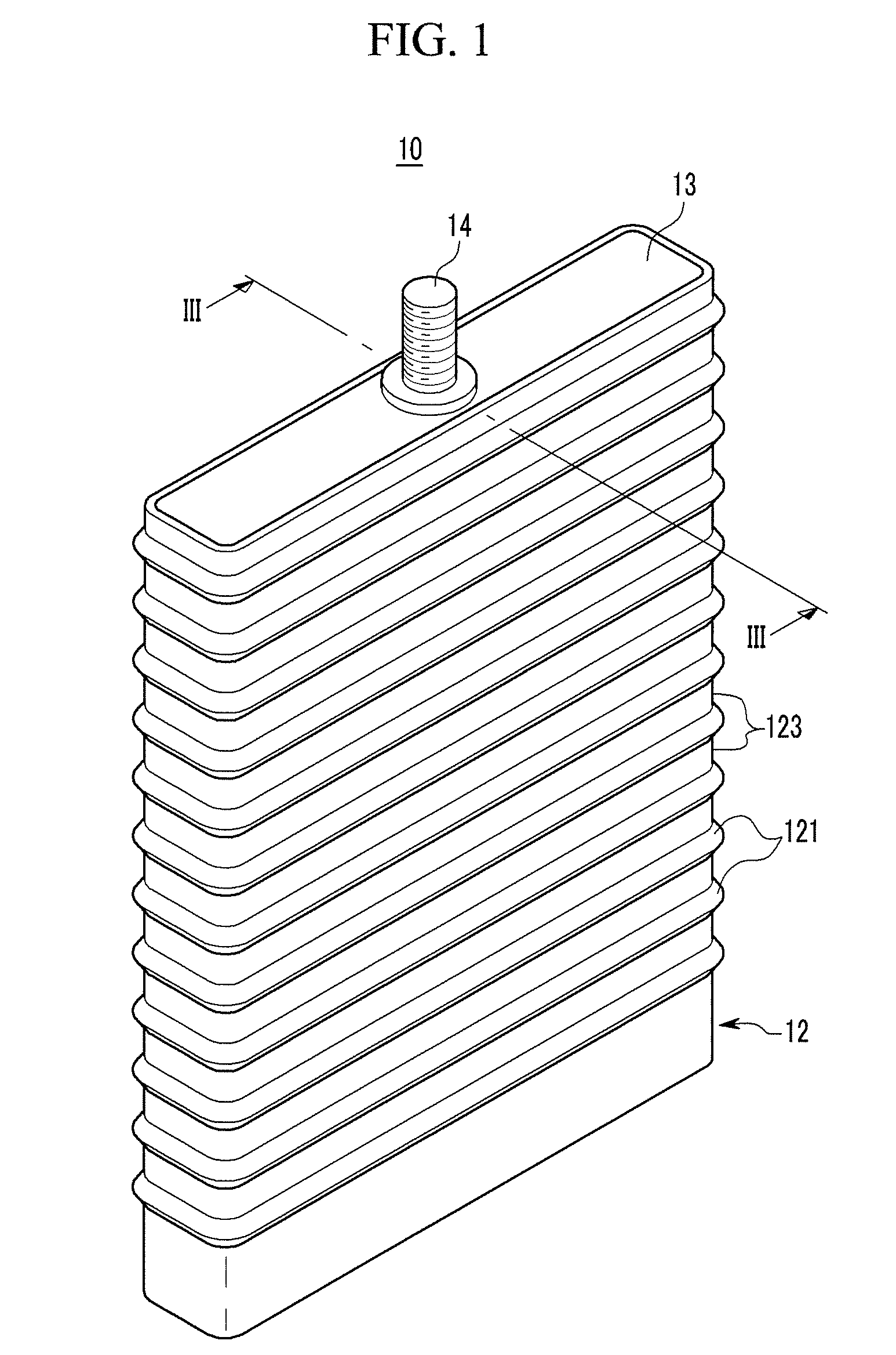
[0055]FIG. 1 is a perspective view of a rechargeable battery according to the present invention, and FIG. 2 is an exploded perspective view of the rechargeable battery shown in FIG. 1.

[0056]Referring to FIG. 1 and FIG. 2, the rechargeable battery 10 includes an electrode assembly 20 where positive and negative electrodes 21 and 22 are wound by interposing an insulating separator 23 therebetween, a case 12 mounting the electrode assembly 20 therein, terminals electrically coupled to the electrode assembly 20, and a first plate 13 fitted to a first opening 125 formed at the case 12.

[0057]The electrode assembly 20 is formed by winding the positive and negative electrodes 21 and 22 while interposing the separator 23 therebetween. After being wound, the electrode assembly 20 is flatly pressed in the shape of a plate, and is folded such that the outer surfaces thereof contact each other. In this way, when the electrode assembly 20 is folded, a tensional force is generated at the innermost...

third embodiment

[0083]FIG. 5 is a cross-sectional view of a rechargeable battery according to the present invention.

[0084]Referring to FIG. 5, a rechargeable battery 60 according to the present embodiment has the same structure as that of the rechargeable battery according to the first embodiment except for the interconnection structure of a case 40, an electrode assembly 20, and a second plate 17, and descriptions of the same structures will not be provided again.

[0085]The case 40 has a quadrangular horizontal section, and a variable region (or case region) 42 with bent units (e.g., peaks and / or valleys) is formed on the circumference of the case 40. That is, the variable region 42 has peaks and / or valleys, e.g., convex portions 42a protruded from the outer surface of the case 40, and concave portions 42b protruded from the inner surface of the case 40.

[0086]The variable region 42 is continuously formed along the circumference of the case 40, and a plurality of units of the variable region 42 are ...

fourth embodiment

[0089]FIG. 6 is a cross-sectional view of a rechargeable battery according to the present invention.

[0090]Referring to FIG. 6, a rechargeable battery 70 according to the present embodiment has the same structure as that of the rechargeable battery according to the first embodiment except for the structure of a case 80, and descriptions of the same structures will not be provided again.

[0091]The case 80 is formed with a quadrangular horizontal section, and has an upper member 81 to which a terminal 14 is fitted, and a lower member 83 connected to the upper member 81 via a variable region 85. However, the present invention is not limited thereto, and the case may be formed with a circular shape or other shapes.

[0092]The variable region 85 accommodates greater elongation than the upper and lower members 81 and 83. The variable region 85 includes a variable plate 851, and a corrosion resistant layer 853 formed on the inner side of the variable plate 851 (on the side thereof facing the e...


PUM

PropertyMeasurementUnit
thicknessaaaaaaaaaa
electrical couplingaaaaaaaaaa
chemical energyaaaaaaaaaa

Abstract

A battery including: a case having a case region extendable along a first direction; an electrode assembly housed within the case and including a first electrode, a second electrode, and a separator between the first electrode and the second electrode, the first electrode including a first uncoated region at a first end of the electrode assembly, and the second electrode including a second uncoated region at a second end of the electrode assembly, the second end facing oppositely away from the first end, and the first uncoated region being spatially separated from the second uncoated region along the first direction; and a terminal electrically coupled to at least one of the first uncoated region or the second uncoated region, the case region being between the first uncoated region and the second uncoated region along the first direction.

Description

CROSS-REFERENCE TO RELATED APPLICATION[0001]This application claims priority to and the benefit of U.S. Provisional Patent Application No. 61 / 157,522 filed Mar. 4, 2009, the entire content of which is incorporated herein by reference.BACKGROUND[0002]1. Field[0003]The following description relates to a rechargeable battery.[0004]2. Description of the Related Art[0005]A rechargeable battery differs from a primary battery in that it can be repeatedly charged and discharged, while the latter only irreversibly converts chemical energy to electrical energy. A low-capacity rechargeable battery is used as a power supply for small electronic devices, such as cellular phones, notebook computers, and camcorders, while a high-capacity rechargeable battery is used as a power supply for driving motors in hybrid vehicles and the like.[0006]A high-power rechargeable battery using a non-aqueous electrolyte with high energy density has been recently developed. For example, the high-power rechargeable...

Claims


Application Information

Patent Timeline
Patent Type & Authority Patents(United States)
IPC IPC(8): H01M2/00H01M2/04H01M50/103H01M50/574
CPCH01M2/34H01M2/0237H01M2/0217H01M2/0232H01M2/0277Y02E60/12Y02E60/10H01M50/103H01M50/174Y02P70/50H01M50/574H01M50/133H01M50/543
Inventor CHEON, SANG-EUNHASHIMOTO, TATSUYAYOO, SEOK-YOONKIM, DONG-WOOKLEE, CHI-YOUNGMOON, JONG-SEOK
Owner ROBERT BOSCH GMBH
Why Eureka
Try Eureka