Power supply switching circuit, real time clock device, electronic apparatus, mobile unit, and method of controlling power supply switching circuit

Active Publication Date: 2014-01-09
SEIKO EPSON CORP
View PDF2 Cites 25 Cited by
  • Summary
  • Abstract
  • Description
  • Claims
  • Application Information

AI Technical Summary

Benefits of technology

[0006]An advantage of some aspects of the invention is to provide a power supply switching circuit, a real time clock device, an electronic apparatus, a mobile un

Problems solved by technology

However, in the circuit configuration described in Patent Document 1, in the case where the load of the load circuit is lighter, when the main power supply is shut down, a current flowing out from the main power supply terminal Vcc via the load circuit to the ground and a current flowing from the backup power supply into the main power supply terminal Vcc may be balanced and, as a result, the voltage of the main power supply terminal Vcc does not become lower and the first switch SW1 remains connected, and a problem that the char

Method used


Image

  • Power supply switching circuit, real time clock device, electronic apparatus, mobile unit, and method of controlling power supply switching circuit
  • Power supply switching circuit, real time clock device, electronic apparatus, mobile unit, and method of controlling power supply switching circuit
  • Power supply switching circuit, real time clock device, electronic apparatus, mobile unit, and method of controlling power supply switching circuit

Examples


first embodiment

1-1. First Embodiment

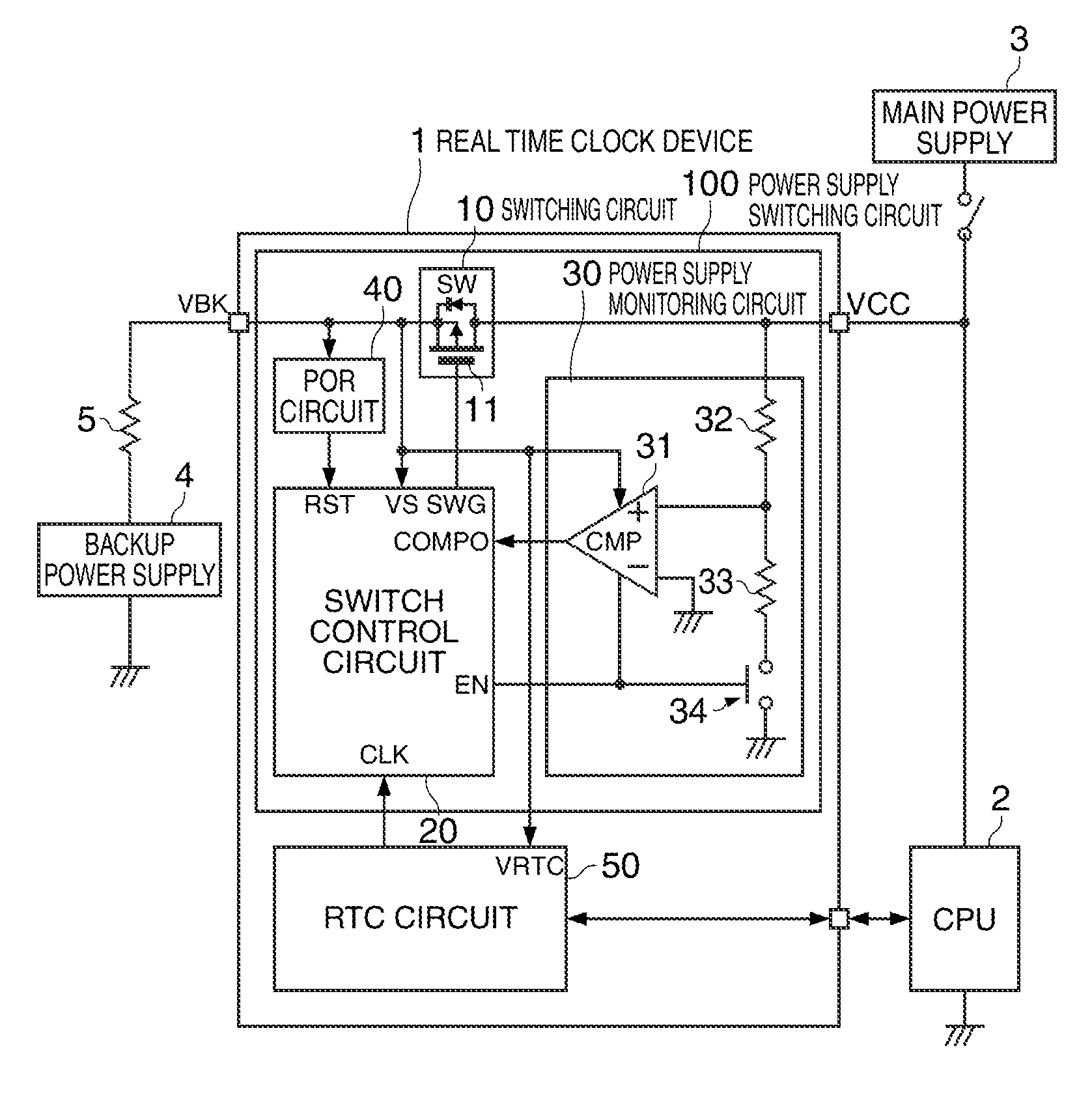
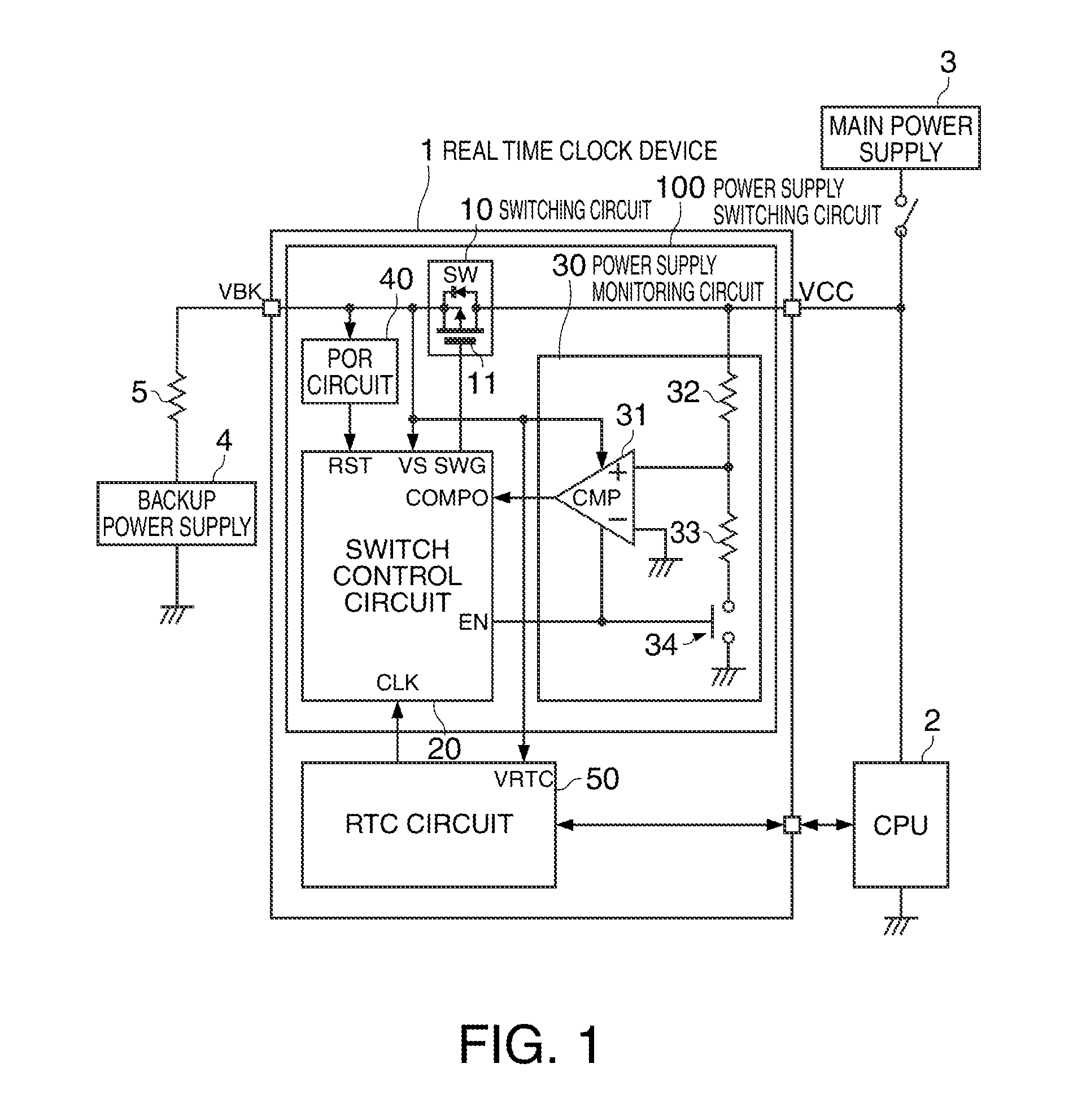
[0056]FIG. 1 shows a configuration example of a real time clock device of the first embodiment. Areal time clock device 1 of the embodiment includes a real time clock (RTC) circuit 50 and a power supply switching circuit 100. Note that the real time clock device 1 of the embodiment may have a configuration in which part of these elements is omitted or changed or another element is added.

[0057]The real time clock device 1 of the embodiment has two power supply terminals of a VCC terminal and a VBK terminal. A main power supply is connected to the VCC terminal and a power supply voltage VCC is supplied from the main power supply. A limiting resistor 5 for limiting the charging rate and a backup power supply 4 such as a secondary cell or a high-capacity capacitor are connected to the VBK terminal.

[0058]The power supply switching circuit 100 includes a switching circuit 10, a switch control circuit 20, a power supply monitoring circuit 30, a power-on reset (POR) cir...

second embodiment

1-2. Second Embodiment

[0090]FIG. 5 shows a configuration example of a real time clock device of the second embodiment. The real time clock device 1 of the embodiment includes a real time clock (RTC) circuit 250 and a power supply switching circuit 200. Note that the real time clock device 1 of the embodiment may have a configuration in which part of these elements is omitted or changed or another element is added.

[0091]The real time clock device 1 of the embodiment has three power supply terminals of a VCC terminal, a VBK terminal, and a VDD terminal. A main power supply is connected to the VCC terminal and a power supply voltage VCC is supplied from the main power supply thereto. A limiting resistor 5 for limiting the charging rate and a backup power supply 4 such as a secondary cell or a high-capacity capacitor are connected to the VBK terminal. The VDD terminal is for outputting a power supply voltage supplied to a circuit and a device (not shown) and a smoothing capacitor 6 is c...


PUM


Abstract

A power supply switching circuit includes a switching circuit that electrically connects a VCC terminal and a VBK terminal in a connected state, a switch control circuit, and a power supply monitoring circuit that monitors a voltage of the VCC terminal, and outputs a voltage of the VBK terminal. The switch control circuit switches a mode from a normal mode in which the switching circuit is intermittently connected to a standby mode in which the switching circuit is opened according to an output signal of the power supply monitoring circuit.

Description

BACKGROUND[0001]1. Technical Field[0002]The present invention relates to a power supply switching circuit, a real time clock device, an electronic apparatus, a mobile unit, and a method of controlling the power supply switching circuit.[0003]2. Related Art[0004]A real time clock (RTC) circuit is a circuit having a timing function and incorporated in various electronic apparatuses such as a personal computer. Generally, the RTC circuit is required to continue timing even when a main power supply of the electronic apparatus is turned off or main power is not supplied temporarily due to instantaneous power interruption, and a power supply switching circuit for detecting shutdown of the main power supply and switching the power supply of the RTC circuit to a backup power supply is provided. As the backup power supply, a primary cell, a secondary cell, a high-capacity capacitor, or the like is used depending on the intended use. In the case where the secondary cell or the high-capacity c...

Claims


Application Information

Patent Timeline
IPC IPC(8): H02J9/06
CPCH02J9/06Y02B70/30Y04S20/20G06F1/263G06F1/30
Inventor KAMIYAMA, MASAYUKIKIYA, HIROSHI
Owner SEIKO EPSON CORP
Why Eureka
Try Eureka