Charging device

a charging device and charging technology, applied in the direction of burglar alarm mechanical actuation, instruments, transportation and packaging, etc., can solve the problems of ineffective utilization of energy for electric products, inability to completely eliminate electromagnetic waves from home appliances, waste of electric power by electric products, etc., to prevent deterioration or destruction, the effect of saving energy

Active Publication Date: 2008-07-24
SEMICON ENERGY LAB CO LTD
View PDF23 Cites 27 Cited by
  • Summary
  • Abstract
  • Description
  • Claims
  • Application Information

AI Technical Summary

Benefits of technology

[0012]In the present invention, surplus radio waves which would normally be left without being used can be converted into electric energy to be reused, which leads to energy saving. In addition, the use of the first protective material makes it possible to prevent deterioration or destruction and malfunction of the rectifier circuit, the power supply circuit, the charge control circuit, and the oscillation circuit which are included in the charging device, and the object to be charged by dielectric heating due to the entry of radio waves, and to supply surplus radio waves as electric energy to the rechargeable battery that is the object to be cha...

Problems solved by technology

However, in fact, it is difficult to totally eliminate electromagnetic waves leaking from home appliances even if a measure to block the electromagnetic waves is taken as in Patent Documents 1 to 3.
Leaking of electromagnetic waves means that energy for electric products cannot be effectively utilized.
Thus, there has been a problem in that ...

Method used


Image

  • Charging device
  • Charging device
  • Charging device

Examples


embodiment mode 1

[0038]A structure of a charging device of the present invention will be described.

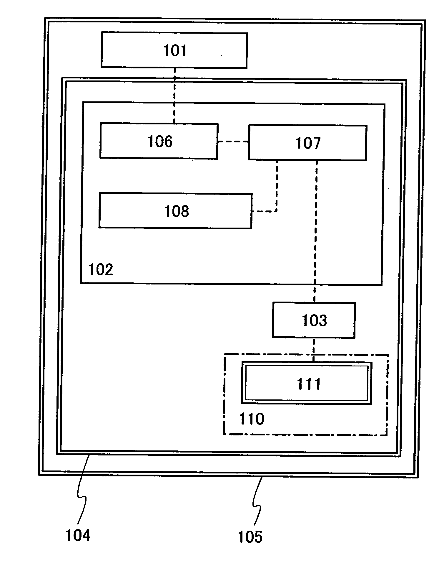
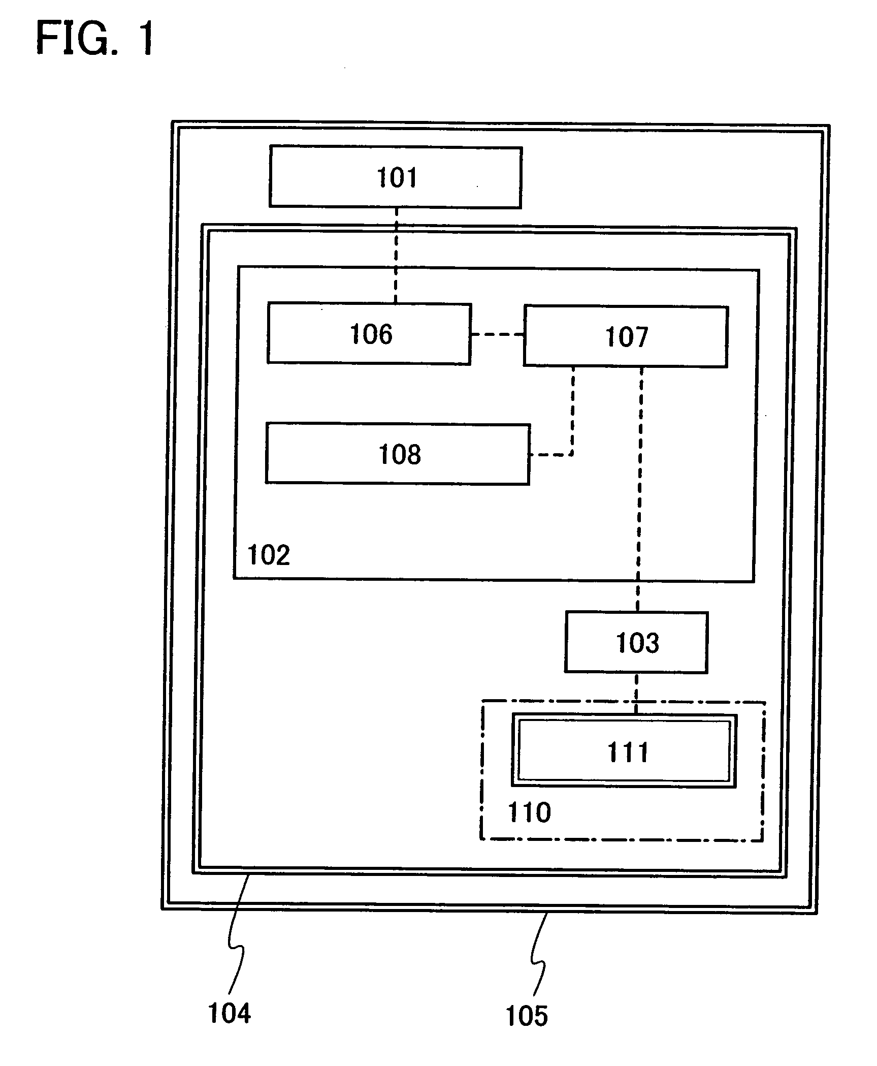
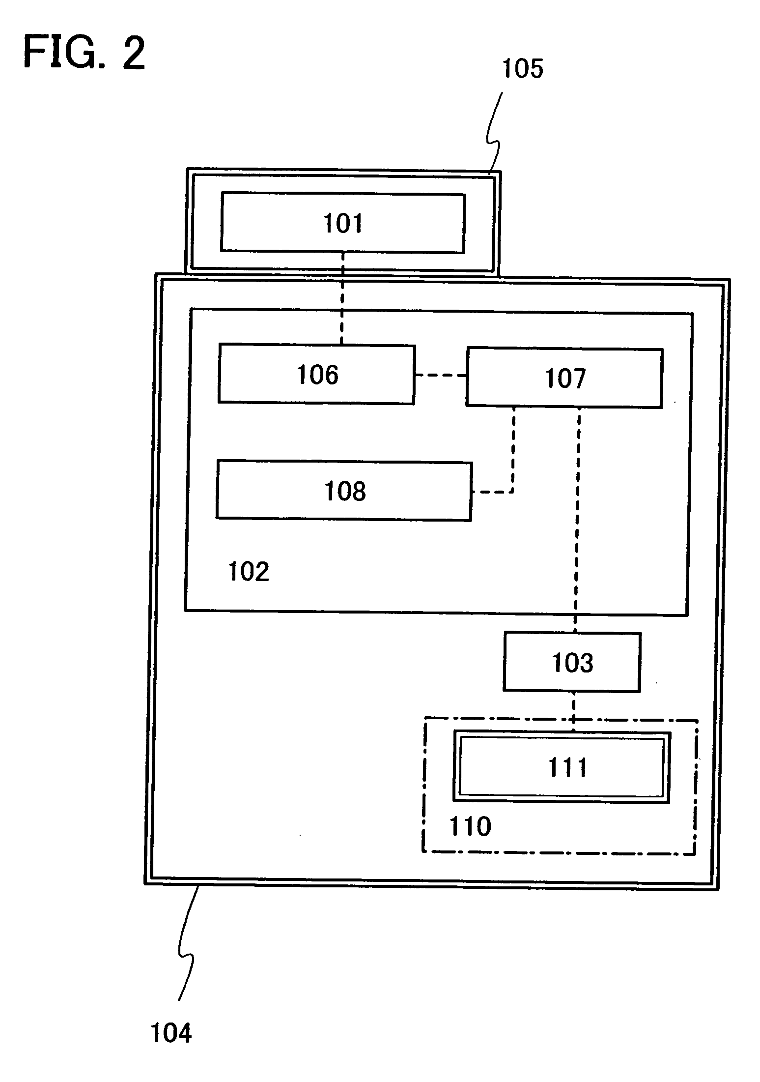
[0039]FIG. 1 is a block diagram showing a structure of the charging device of the present invention as an example. The charging device shown in FIG. 1 includes an antenna circuit 101, a charging circuit 102, a terminal 103, a first protective material 104, and a second protective material 105. The charging circuit 102 includes a rectifier circuit 106, a power supply circuit 107, and a charge control circuit 108.

[0040]In addition, FIG. 1 shows an object to be charged 110 which receives supply of electric energy from the charging device of the present invention. The object to be charged 110 is stored in a storage portion with connected to the terminal 103. The terminal 103 may be provided in the storage portion or outside the storage portion. The object to be charged 110 includes a rechargeable battery 111, and the object to be charged 110 can be charged with the use of electric energy from the charging ...

embodiment mode 2

[0051]A structure of a charging device of the present invention will be described. FIG. 3 is a block diagram showing a structure of a charging device of the present invention as an example. The charging device shown in FIG. 3 includes a first antenna circuit 201, a charging circuit 202, a second antenna circuit 203, a first protective material 204, and a second protective material 205. The charging circuit 202 includes a rectifier circuit 206, a power supply circuit 207, an oscillation circuit 208, and an oscillation control circuit 209.

[0052]In addition, an object to be charged 210 that is an electronic appliance which receives supply of electric power from the charging device of the present invention is shown in FIG. 3. The object to be charged 210 includes a third antenna circuit 211, a charging circuit 212, and a rechargeable battery 213. The object to be charged 210 can be charged wirelessly with the use of electric energy from the charging device. The object to be charged 210 ...

embodiment mode 3

[0066]In this embodiment mode, a specific structure of the charging device of the present invention described in Embodiment Mode 1 or 2 will be described.

[0067]An outer appearance of the charging device of the present invention is shown as an example in FIGS. 5A to 5C. FIG. 5A is a perspective view of the charging device of the present invention. A housing 301 functions as a first protective material. The housing 301 includes a lid 304 which is openable and closable when an object to be charged is taken in and out of the housing 301. An antenna circuit or a first antenna circuit (hereinafter, in this embodiment, referred to as an antenna circuit) 302 is provided for the housing 301, and a second protective material 303 is provided so as to cover the antenna circuit 302.

[0068]FIG. 5B shows a state in which the second protective material 303 is removed from the charging device shown in FIG. 5A. Note that, although an example in which a dipole antenna is used for the antenna circuit 30...


PUM


Abstract

The charging circuit includes an antenna circuit receiving radio waves, a rectifier circuit rectifying AC voltage generated in the antenna circuit to generate DC voltage, and a power supply circuit adjusting the magnitude of the DC voltage and charging a rechargeable battery using the adjusted DC voltage. The charging device may further include a charge control circuit controlling the power supply circuit so as to prevent overcharge of the rechargeable battery. The rechargeable battery may be charged by application of DC voltage to a pair of terminals, or it may be charged wirelessly in such a manner that an oscillation circuit and an output antenna circuit are additionally provided.

Description

BACKGROUND OF THE INVENTION[0001]1. Field of the Invention[0002]The present invention relates to a charging device which receives supply of electric power wirelessly.[0003]2. Description of the Related Art[0004]There are various home appliances which use electric power as an energy source, and they penetrate deeply into our lives as essentials. These home appliances include devices which mechanically operate by electric energy, such as motors, high-frequency devices which generate high frequency waves using electric energy, and the like. Thus, when home appliances are used, an electromagnetic field is generated around the home appliances.[0005]In particular, a high-frequency heating apparatus using a high-frequency device, such as a microwave, has a feature of being capable of heating an object to be processed, such as food, by dielectric heating with electromagnetic waves. However, there has been a problem in that part of electromagnetic waves has not been absorbed by an object to ...

Claims


Application Information

Patent Timeline
IPC IPC(8): H02J7/00
CPCH02J7/0042H05B6/76H02J17/00H02J50/12H02J50/20H02J50/70H02J50/402
Inventor TAMURA, HIKARU
Owner SEMICON ENERGY LAB CO LTD
Why Eureka
Try Eureka