Process for catalytic reforming

a technology of catalytic reforming and catalyst, applied in the direction of chemistry apparatus and processes, hydrogen separation by selective and reversible uptake, inorganic chemistry, etc., can solve the problems of increasing reducing compressor energy consumption, and preventing contamination and poisoning. , the effect of reducing the energy consumption of compressors

Active Publication Date: 2015-03-26
UOP LLC
View PDF1 Cites 9 Cited by
  • Summary
  • Abstract
  • Description
  • Claims
  • Application Information

AI Technical Summary

Benefits of technology

The invention reduces energy usage by eliminating heavy molecules from a recycled gas that enters a compressor's suction. This also prevents damage to downstream catalysts used for refining. By passing through a membrane, the recycled gas has a similar chemical makeup to the incoming gas, which helps maintain consistent operation.

Problems solved by technology

The technical problem addressed in this patent text relates to improving the performance of hydrogen recovery systems used in petroleum and petrochemical industries. Current systems often struggle to effectively separate out heavy compounds like nitrogen and carbon dioxide, which leads to increased energy usage and potential damage to downstream equipment when combining recovered hydrogen gases. There is thus a need for new methods that address these issues and improve overall efficiency and reliability of hydrogen recovery operations.

Method used


Image

  • Process for catalytic reforming
  • Process for catalytic reforming

Examples


Embodiment Construction

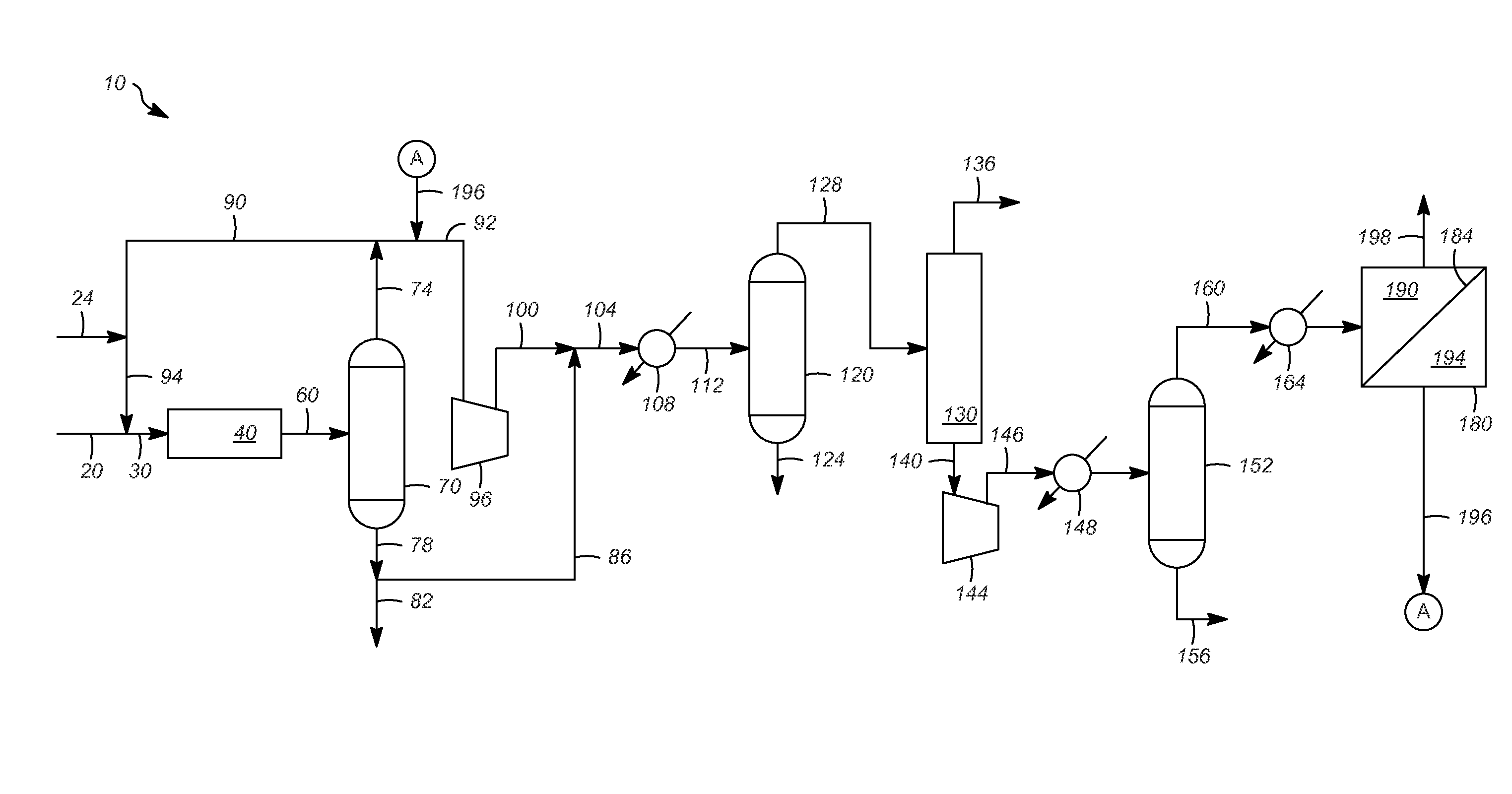
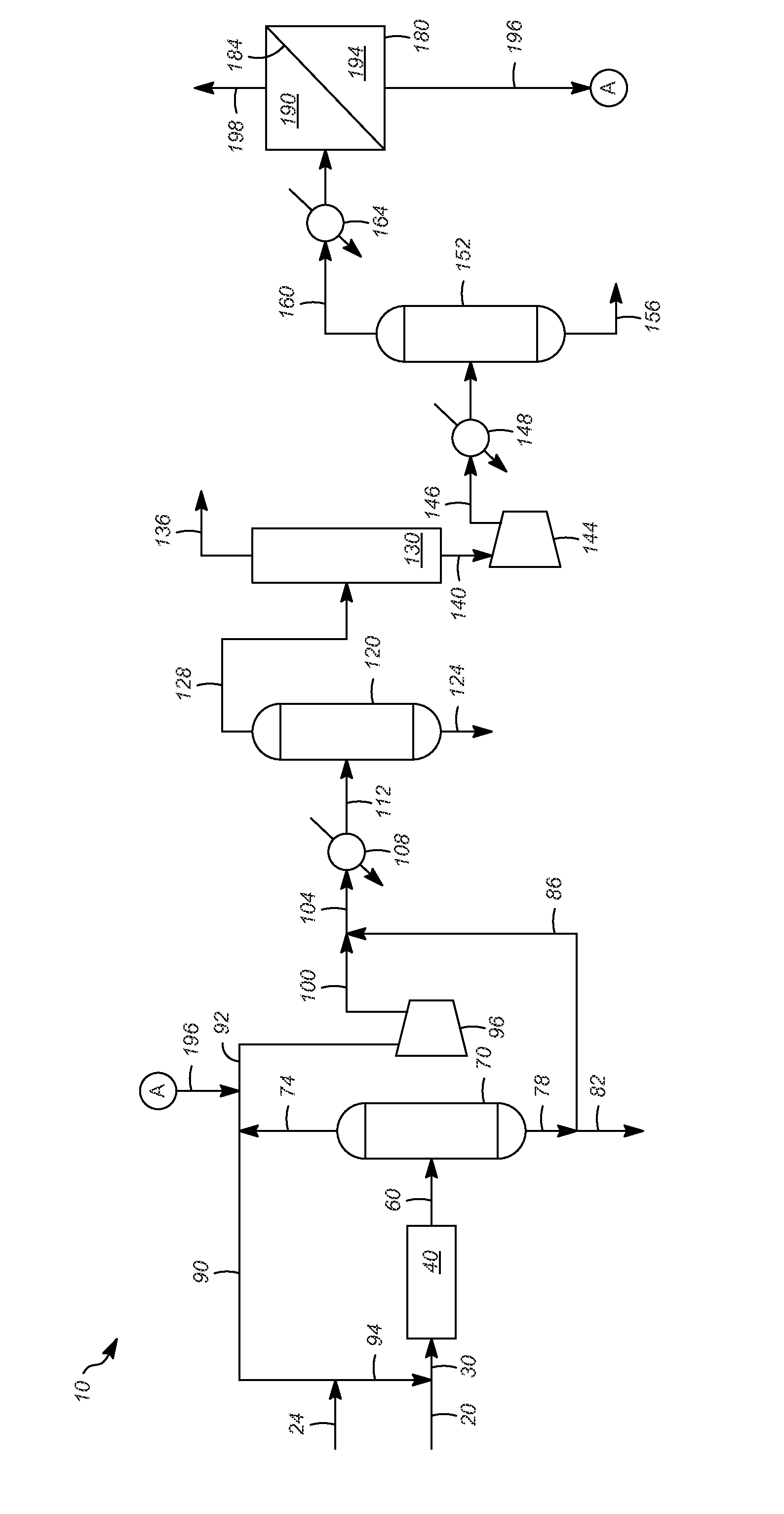
[0018]Referring to the FIGURE, a catalytic reforming zone 10 can include a reaction zone 40, a separation zone or a first separation zone 70, a vessel or a first vessel 120, an adsorption zone 130, another vessel or a second vessel 152, and another separation zone or a second separation zone 180. Generally, the catalytic reforming zone 10 uses single or multiple reaction zones with catalyst particles disposed as fixed beds or movable via gravity flow. Exemplary reforming reaction zones are disclosed in, e.g., US 2011 / 0147270 and U.S. Pat. No. 6,350,371. The reforming process can be particularly applicable to the treatment of straight-run gasolines including relatively large concentrations of naphthenic and substantially straight-chain paraffinic hydrocarbons that may be amenable to aromatization through dehydrogenation and / or cyclization. To summarize, various other concomitant reactions also occur, such as isomerization and hydrogen transfer, which are beneficial in upgrading the a...


PUM


Abstract

One exemplary embodiment can be a process for catalytic reforming The process can include catalytically reforming a hydrocarbon feed in a reaction zone, obtaining an effluent stream having hydrogen and hydrocarbons from the reaction zone, obtaining from at least a portion of the effluent stream a waste hydrocarbon stream from an adsorption zone, passing at least a portion of the waste hydrocarbon stream as a feed stream across a feed side of a membrane having the feed side and a permeate side, and being selective for hydrogen over one or more C1-C6 hydrocarbons, and withdrawing from the permeate side a permeate stream enriched in hydrogen compared with a residue stream withdrawn from the feed side.

Description


Claims


Application Information

Patent Timeline
Owner UOP LLC
Why Eureka
Try Eureka