
Ultrasonic surgical instrument with dual end effector

a surgical instrument and dual-end technology, applied in the field of ultrasonic surgical instruments, can solve the problems of difficult to initiate and direct a cut, the ability to create a curved or compound angle cut is extremely limited, and the significant thickness of viable bone is lost in the cutting procedure, so as to improve the cutting ability

Inactive Publication Date: 2015-03-26
MISONIX INC
View PDF9 Cites 28 Cited by
  • Summary
  • Abstract
  • Description
  • Claims
  • Application Information

AI Technical Summary

Benefits of technology

This patent is about an ultrasonic bone cutting instrument that is designed to be faster and more efficient. It features a cooling system to prevent thermal damage to living tissue and can make complex cuts. The instrument consists of at least two cutting blades that are driven out of phase with each other to improve cutting performance. The instrument can be used in surgery and has one or more continuous cutting surfaces. Overall, this patent introduces a new way to use ultrasonic technology for bone cutting.

Problems solved by technology

While traditional saws are functional, they have many disadvantages.
With either the band or reciprocating saws, for instance, it is not easy to initiate and direct a cut.
With all blades the ability to create a curved or compound angle cut is extremely limited by the blade chosen.
The relatively thick blades have a wide kerf; so that a significant thickness of the viable bone is lost in the cutting procedure.
Above all, the relatively slow linear or tangential speeds of conventional bone saw blades coupled with the teeth necessary for cutting result in high frictional losses, which becomes manifested as heat.
While these devices are superior to the traditional saws in several aspects such as reduced kerf size, reduced noise, and superior ability for making complex geometric cuts, the temperature rise in bone due to frictional heating at the blade / tissue interface is still a significant problem.
The problem is exacerbated with the use of ultrasonics due to the rapid motion involved as compared to that of traditional reciprocating saws.

Method used


Image

  • Ultrasonic surgical instrument with dual end effector
  • Ultrasonic surgical instrument with dual end effector
  • Ultrasonic surgical instrument with dual end effector

Examples


Embodiment Construction

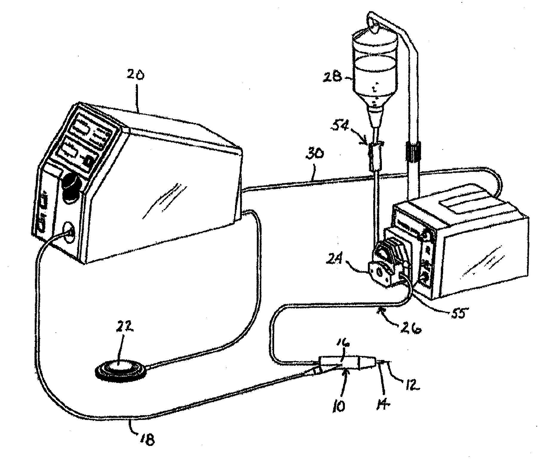
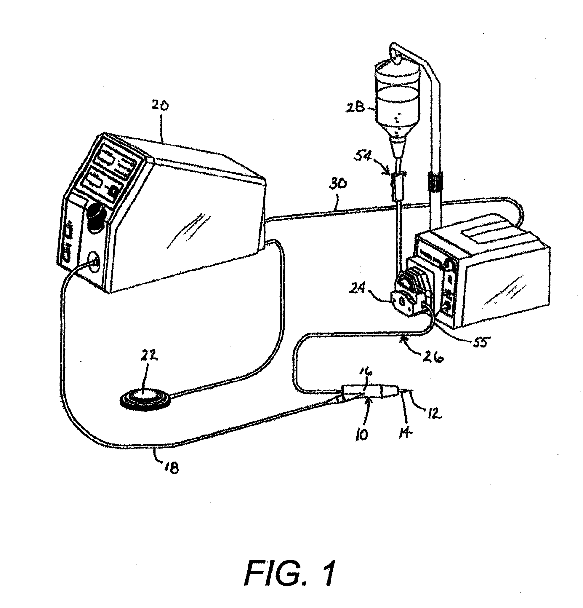
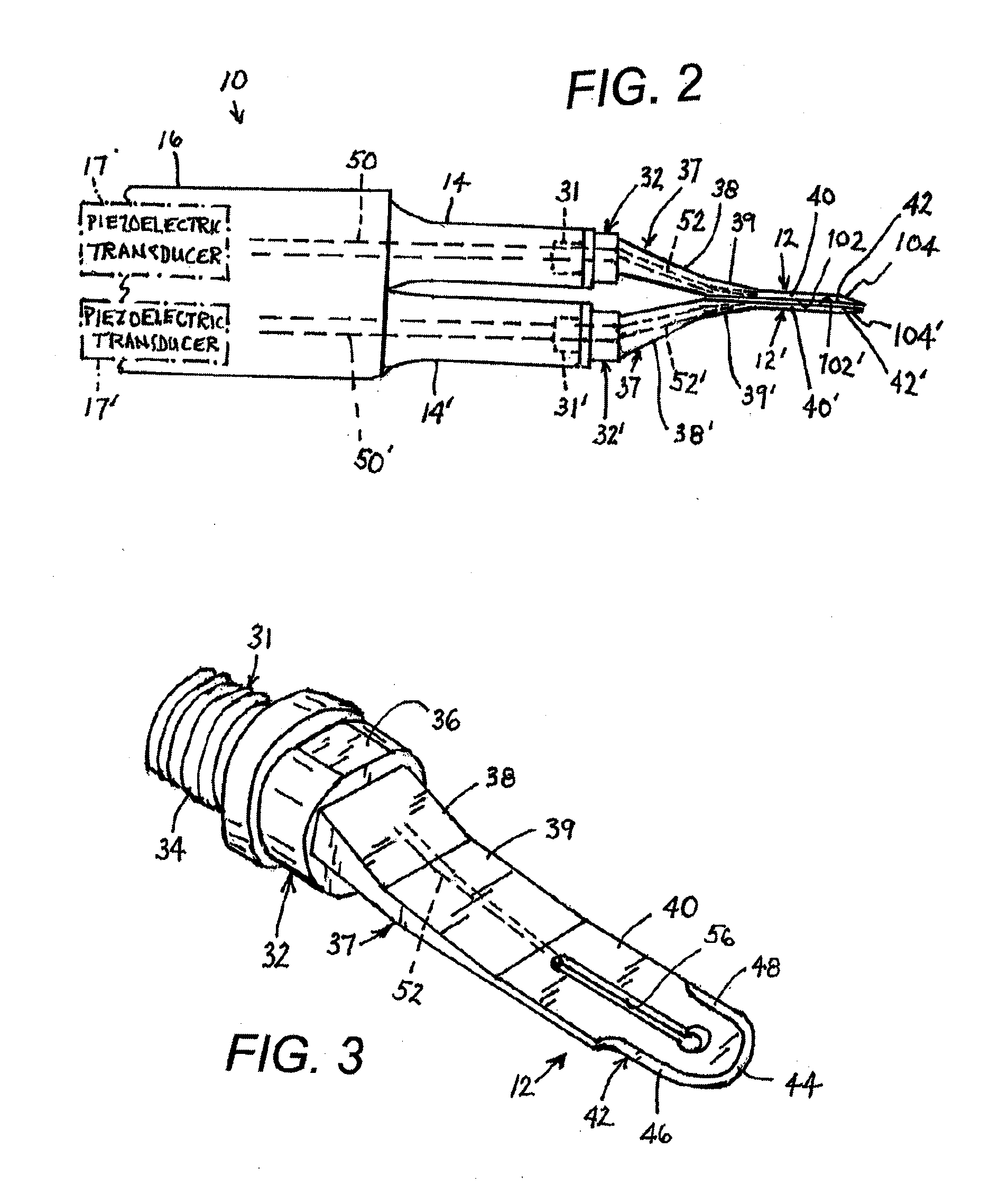
[0028]As shown in FIGS. 1 and 2, an ultrasonic surgical system includes a handpiece 10 carrying a pair of laterally juxtaposed tools in the form of bone cutting blades 12 and 12′ disposed in parallel to one another. Handpiece 10 is attached to blades 12 and 12′ via respective probes 14 and 14′ and further includes a housing 16 which encases two piezoelectric crystal assemblies 17 and 17′ each of the kind disclosed in U.S. Pat. No. 5,371,429 to Manna. In response to two sinusoidal oscillating signals transmitted over a cable 18 from an ultrasonic generator 20, the crystal assemblies 17 and 17′ in the handpiece produce longitudinal ultrasonic pressure waves transmitted through probes 14 and 14′ to blades 12 and 12′. Signal generator 20 is activated via a footswitch 22. Handpiece 10 is also connected to an irrigation pump 24 via a tube 26. Pump 24 moves an irrigant liquid from a reservoir or IV type hanging bag 28 through tube 26 to handpiece 10 in response to a signal carried over a c...


PUM


Abstract

An ultrasonic surgical instrument includes at least two tools each having a respective operating head with an operative surface or edge. At least one source of ultrasonic mechanical vibratory energy is provided which produces at least two vibration modes out of phase with one another. The tools are each connected to the source of ultrasonic mechanical vibratory energy for enabling transmission of a respective one of the vibration modes into the respective tool so that the tools are driven out of phase with one another.

Description

FIELD OF THE INVENTION[0001]This invention relates to an ultrasonic surgical instrument. More particularly, this invention relates to an ultrasonic surgical instrument with dual end effectors. Where the instrument particularly takes the form of an instrument to cut tissue such as cartilage and bone, the dual end effectors are parallel cutting blades.BACKGROUND OF THE INVENTION[0002]In the field of orthopedics, the cutting of living bone is a prerequisite for many procedures. Such procedures include the reconstruction of damaged tissue structures due to accidents, the grafting of healthy bone into areas damaged by disease, or the correction of congenital facial abnormalities like a receding chin line. Over several centuries, these tasks were performed through the utilization of devices called bone saws.[0003]Traditional bone saws are categorized into several basic categories. Hand powered saws or drills are just that, hand held devices which require the operator to move the device in...

Claims


Application Information

Patent Timeline
Patent Type & Authority Applications(United States)
IPC IPC(8): A61B17/16A61B17/32
CPCA61B17/16A61B2017/1651A61B17/320068A61B17/142A61B2017/32007A61B2017/320074
Inventor MANNA, RONALD
Owner MISONIX INC
Learn More