Mobile robot with returning mechanism

Inactive Publication Date: 2015-03-26
ELECTRONICS & TELECOMM RES INST
View PDF4 Cites 33 Cited by
  • Summary
  • Abstract
  • Description
  • Claims
  • Application Information

AI Technical Summary

Benefits of technology

[0008]In accordance with any one of solutions to the subject described above, it is possible to implement a method to return the mobile robot by use of the tension of the returning me

Problems solved by technology

However, in the provision of the method to return the mobile robot, the aforementioned prior art does not disclose how to return a mobile robot to an initial starting point when the communication between a moving body and a remote control device is disconnected.

Method used


Image

  • Mobile robot with returning mechanism
  • Mobile robot with returning mechanism
  • Mobile robot with returning mechanism

Examples


first embodiment

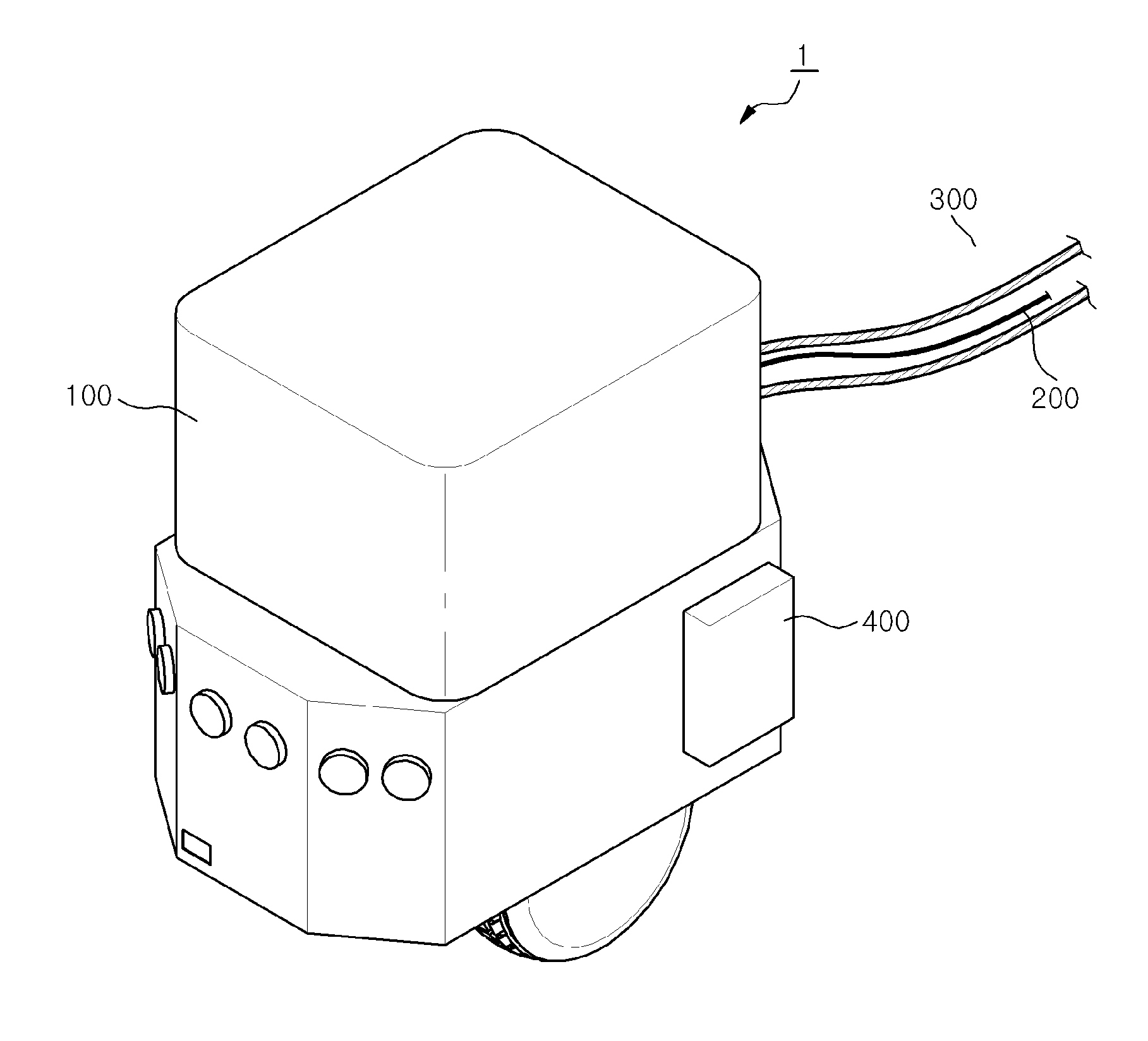
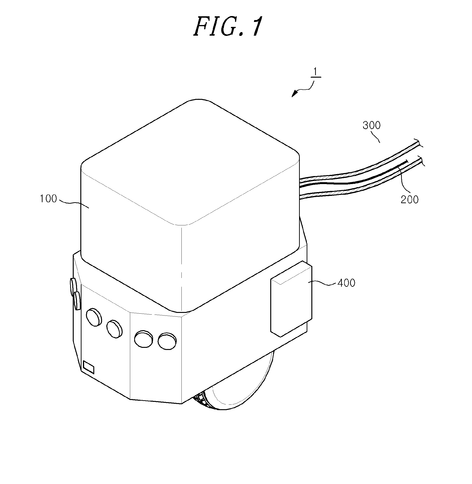
[0027]FIGS. 3A and 3B show perspective views of a mobile robot having a returning mechanism in accordance with the present invention. Referring to FIGS. 3A and 3B, the moving member 100 may be one of ballcasters, wheel-based ballcasters and fixed flippers.

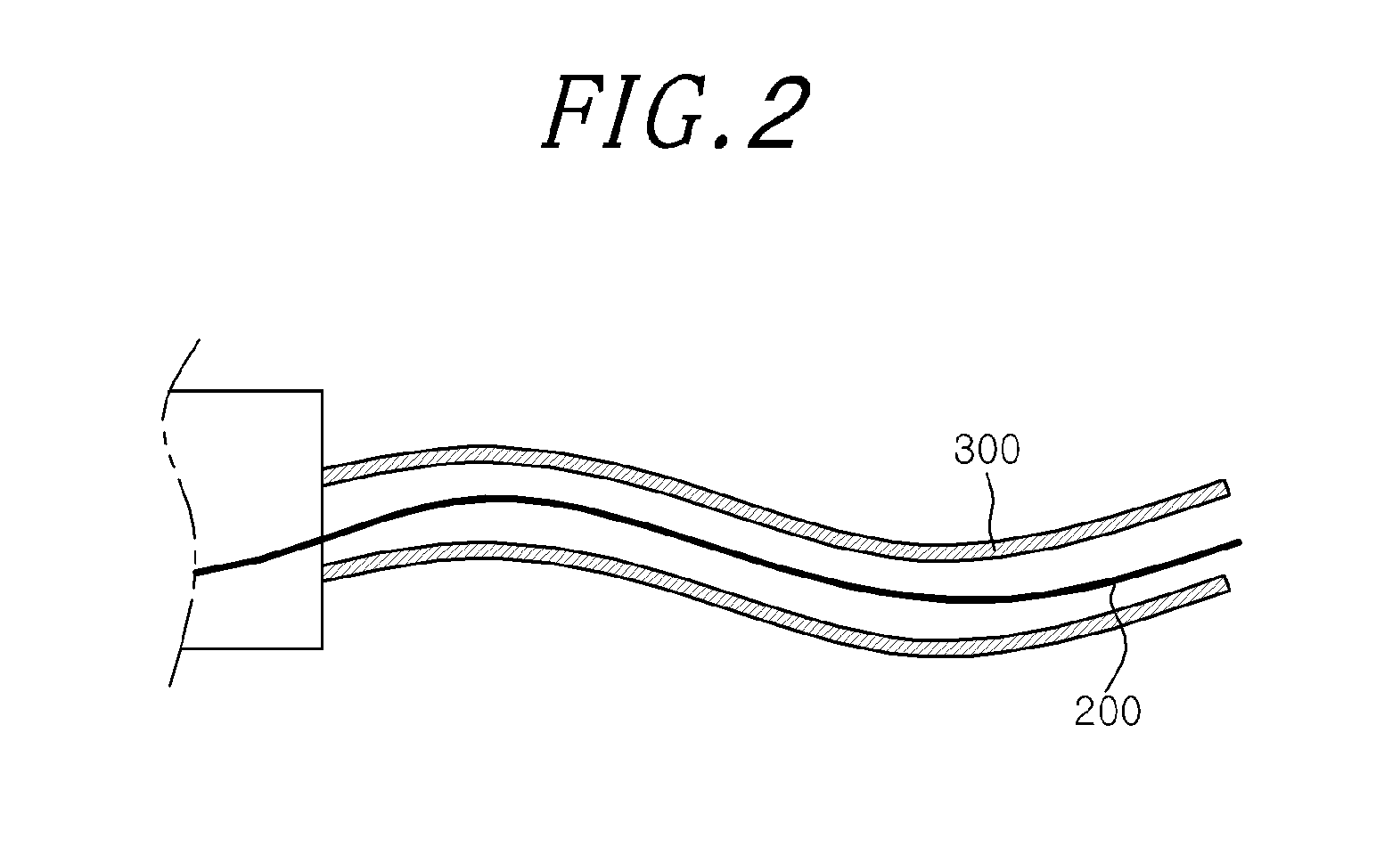
[0028]The mobile robot 1 having a returning mechanism in accordance with an embodiment of the present invention can be returned by pulling on the returning member 300 in a situation where it cannot move by itself due to breakdown. However, because the gear ratio between a motor and wheels that are engaged is high, the wheels do not rotate easily once the motor is stopped, which leads to a difficult of returning the mobile robot.

[0029]In accordance with a first embodiment of the present invention, therefore, a plurality of the moving members 100 enable to easily move without employing the wheels. For example, although the mobile robot 1 having a returning mechanism falls down on its side, it is possible to return the mobile robot 1 ...

fourth embodiment

[0037]FIGS. 6A and 6B are a side view of a mobile robot having a returning mechanism in accordance with the present invention. Referring to FIG. 1 and FIGS. 6A and 6B, the mobile robot 1 having a returning mechanism further includes one or more gears 900, a primary motor 930 and a control unit 600.

[0038]The one or more gears 900 are coupled to a moving unit 910 of the mobile robot 1. The moving unit 910 may be one or more wheels of the mobile robot 1.

[0039]The primary motor 930 is engaged with the gear 900 to drive the moving unit 910.

[0040]The control unit 600 detects a state that the mobile robot 1 is not able to move. When the control unit 600 detects the state that the mobile robot 1 is not able to move, it forces the primary motor 930 to be separated from the gear 900 by moving the primary motor 930 in one side direction.

[0041]The mobile robot 1 having a returning mechanism in accordance with the fourth embodiment of the present invention separates the primary motor 930 from th...

fifth embodiment

[0042]FIGS. 7A and 7B show perspective views of a mobile robot having a returning mechanism in accordance with the present invention. The operation of the mobile robot of FIGS. 7A and 7B will be explained with reference to FIG. 1 as below. The mobile robot 1 having a returning mechanism includes a caterpillar 910 as the moving unit, and further includes a control unit 600 and linear motor 700.

[0043]The caterpillar 910 includes one or more main moving rollers 911, an at least subsidiary moving roller 913, and a belt assembly 915 in which a plurality of plates is coupled using pins enclosing the main moving roller 911 and the subsidiary moving roller 913.

[0044]The control unit 600 detects a state that the mobile robot 1 is not able to move, and a linear motor 700 is connected with the caterpillar 910. When the control unit 600 detects the state that the mobile robot 1 is not able to move, it drives the linear motor 700 to remove the pins on the belt assembly 915. Or, when the control ...


PUM


Abstract

A mobile robot having a returning mechanism includes one or more moving members mounted on a body of the mobile robot; and a cable member connected to one side of the mobile robot so as to supply the mobile robot with electrical power. Further, the mobile robot includes a returning member having a rigidity stronger than the cable member and disposed to wrap the cable member so that the cable member is placed within the returning member; and a take-up unit configured to pull the returning member to keep it taut.

Description

CROSS-REFERENCE TO RELATED APPLICATION(S)[0001]The present invention claims priority of Korean Patent Application No. 10-2013-0114335, filed on Sep. 26, 2013, which is incorporated herein by reference.FIELD OF THE INVENTION[0002]The present invention relates to a mobile robot having a returning mechanism, and more specifically, to a method and apparatus for returning a mobile robot to an initial location from a hazardous area at a situation where the mobile robot cannot be remotely controlled.BACKGROUND OF THE INVENTION[0003]In recent years, there has been proposed a method to deploy a mobile robot in an area where people do not access directly because of a lot of hazardous factors such as radioactive area and remotely control the mobile robot to accomplish the intended task.[0004]After that, a method of returning the mobile robot to an origin point is performed by a method using image information. In connection with the method of returning a moving body, a prior art of Korean Paten...

Claims


Application Information

Patent Timeline
IPC IPC(8): G05D1/02
CPCY10S901/01G05D1/0225G05D2201/0207B25J19/06B25J5/00
Inventor CHOI, SUNGLOKYUN, WOO HANPARK, JAE HYUNPARK, SEUNGHWANYU, WONPILLEE, YU-CHEOL
Owner ELECTRONICS & TELECOMM RES INST
Why Eureka
Try Eureka