

Touch display device and method for driving the same
a display device and touch technology, applied in the field of touch display devices, can solve the problems of inability to accurately determine the touch or touch area, reduce image quality, etc., and achieve the effect of reducing power consumption, sufficient ensuring gate driving time and touch sensing tim
- Summary
- Abstract
- Description
- Claims
- Application Information
AI Technical Summary
Benefits of technology
Problems solved by technology
Method used
Image

Examples
first embodiment
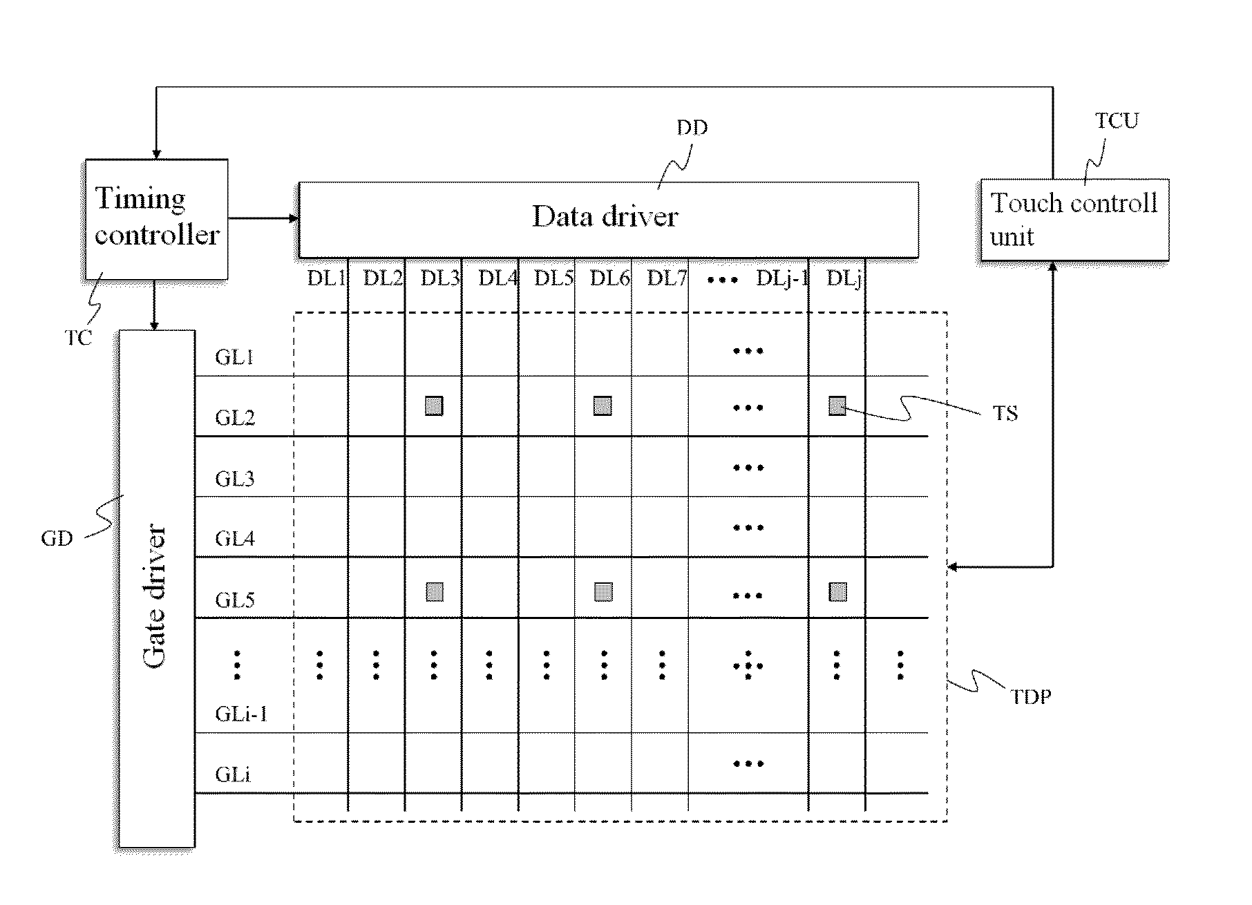
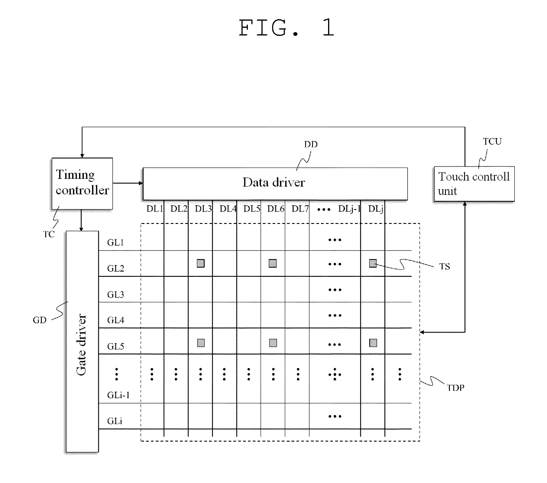
[0021]FIG. 1 is a block diagram of a touch display device according to the present invention.
[0022]As illustrated in FIG. 1, the touch display device according to the first embodiment of the present invention includes a touch display panel TDP, a touch control unit TCU, a timing controller TC, a gate driver GD, and a data driver DD.
[0023]The touch display panel TDP displays an image corresponding to image data input to the touch display panel TDP through the timing controller TC and the data driver DD, and also displays an image corresponding to a touch applied from outside the touch display device. To this end, the touch display panel TDP includes n pixels (n is a natural number greater than 1) for displaying an image and m touch sensors TS (m is a natural number greater than 1) for sensing a touch applied from outside the touch display device. One touch sensor TS is formed for k pixels (k is a natural number greater than 1) in the touch display panel TDP. Here, the n pixels are re...
second embodiment
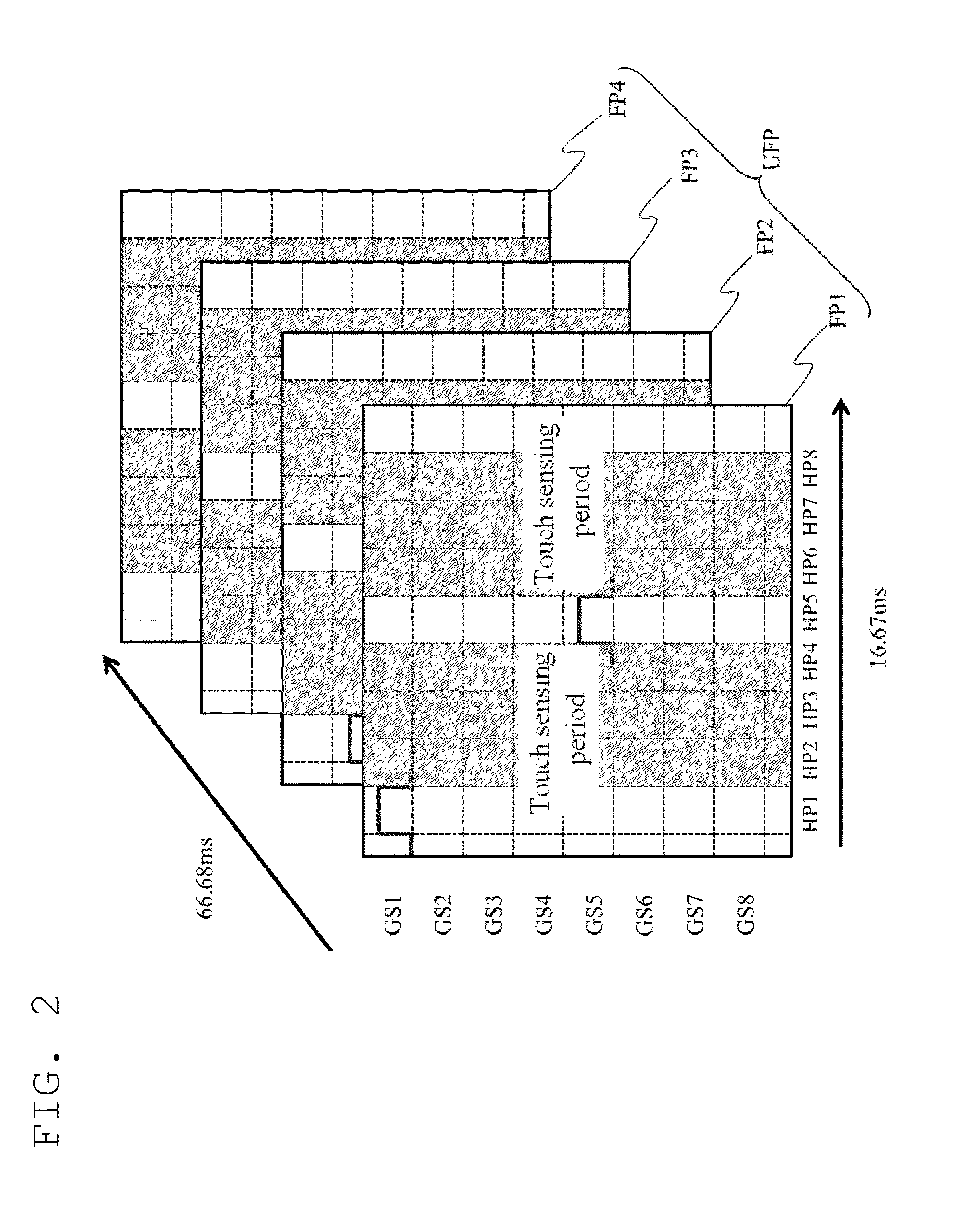
[0035]FIG. 5 is a diagram for describing a method for driving a touch display device according to the present invention. Here, for convenience of explanation, only a few gate lines (e.g., eight gate lines GL1 to GL8) are illustrated in FIG. 5.
[0036]The method according to the second embodiment of the present invention uses another interlaced scan mode and, more particularly, a 4field-1scan-3skip type interlaced scan mode in which one unit field period UFP includes four continuous field periods FP1 to FP4, all gate lines GL1 to GLi are driven during the first field period FP1, and no gate line is driven during the other second to fourth field periods FP2 to FP4.
[0037]As illustrated in FIG. 5, the gate driver GD operating according to the 4field-1scan-3skip type interlaced scan mode sequentially drives all gate lines GL1 to GLi by providing i gate signals (all gate signals including GL1 to GL8) to the gate lines GL1 to GLi during the first field period FP1, and drives no gate line dur...
third embodiment
[0038]FIG. 6 is a diagram for describing a method for driving a touch display device according to the present invention. Here, for convenience of explanation, only a few gate lines (e.g., eight gate lines GL1 to GL8) are illustrated in FIG. 6.
[0039]The method according to the third embodiment of the present invention uses another interlaced scan mode and, more particularly, a 4field-2scan-2skip type interlaced scan mode in which one unit field period UFP includes four continuous field periods FP1 to FP4, i / 2 gate lines are driven in each of the first and third field periods FP1 and FP3, and no gate line is driven in the other second and fourth field periods FP2 and FP4.
[0040]As illustrated in FIG. 6, the gate driver GD operating according to the 4field-2scan-2skip type interlaced scan mode sequentially drives (2n+1)th gate lines GL1, GL3, GL5, and GL7 by providing (2n+1)th gate signals GS1, GS3, GS5, and GS7 respectively to the (2n+1)th gate lines GL1, GL3, GL5, and GL7 during the f...
PUM
 Abstract
Description
Claims
Application Information