Zoom lens and imaging apparatus

a zoom lens and imaging apparatus technology, applied in the field of zoom lens and imaging apparatus, can solve the problems of difficult widening of increased weight of the lens system, and increased difficulty in widening so as to enhance the advantageous effect, widen the angle of view, and favorably correct the variations of the imaging plane

Inactive Publication Date: 2015-04-02
FUJIFILM CORP
View PDF1 Cites 20 Cited by
  • Summary
  • Abstract
  • Description
  • Claims
  • Application Information

AI Technical Summary

Benefits of technology

[0020]Dg34min: the minimum value of the distance between the third lens group and the fourth lens group while changing magnification.
[0101]Further, it is preferable for the zoom lens of the present embodiment to satisfy conditional formula (2) below.
[0105]Conditional formula (2) defines an appropriate difference between the maximum value and the minimum value of the distances between two lens groups which are floating groups, with respect to the focal length of the third lens group G3. Setting the value of (Dg34max−Dg34min)/f3 to fall below the lower limit defined by conditional formula (2) will make the converging effect on light rays by the third lens group G3 insufficient. Thereby, widening the angle of view will be difficult.
[0106]It is more preferable for conditional formula (2-1) below to be satisfied to enhance the advantageous effect described above.
[0107]As described above, according to the zoom lens of the present embodiment, the zoom lens is of a five-group configuration as a whole and the configuration of each lens group is suitably set. Further, the zoom lens adopts a floating system in which the third lens group G3 and the fourth lens group G4 correct variations in the imaging plane due to

Problems solved by technology

Thereby, when a wider angle of view is achieved, the lens system will become larger and the weight thereof will also increase.
This makes it difficult to widen the angle of view.
Meanwhile, con

Method used


Image

  • Zoom lens and imaging apparatus
  • Zoom lens and imaging apparatus
  • Zoom lens and imaging apparatus

Examples


example 1

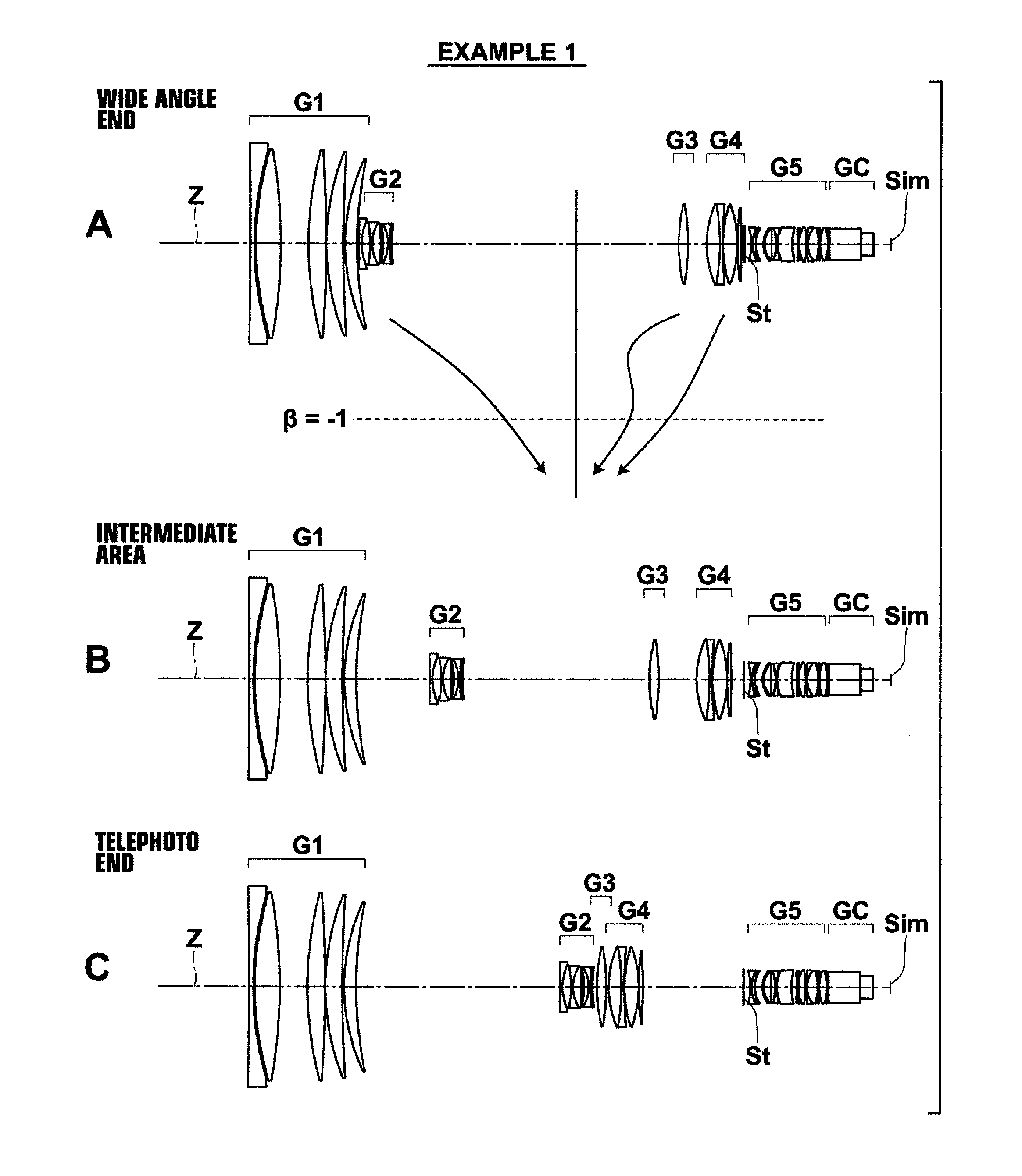
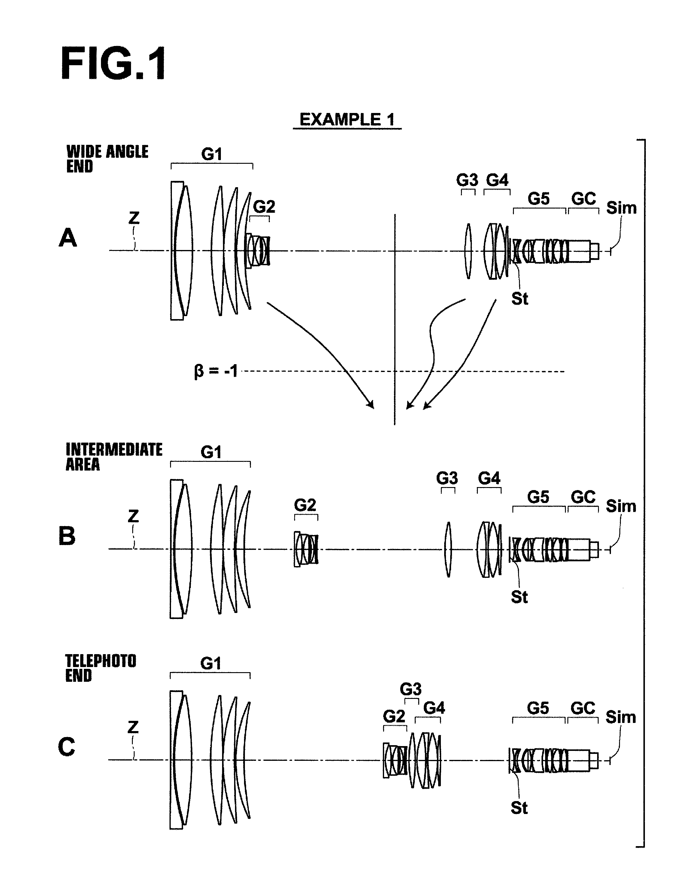
[0109]The cross sectional view of the lens of Example 1 is shown in FIG. 1. Detailed configurations thereof are shown in FIGS. 7 through 9. FIG. 7 shows detailed configurations of the first lens group G1 and the second lens group G2, FIG. 8 shows detailed configurations of the third lens group G3 and the fourth lens group G4, and FIG. 9 shows detailed descriptions from the fifth lens group G5 to the image formation surface Sim.

[0110]In Example 1, the first lens group G1 is of a five-lens configuration including lenses L1 through L5, the second lens group G2 is of a six-lens configuration including lenses L21 through L26, the third lens group G3 is of a one-lens configuration including a lens L31, the fourth lens group G4 is of a four-lens configuration including lenses L41 through L44, and a fifth lens group G5 is of a thirteen-lens configuration including an aperture stop St and lenses L51 through L63.

[0111]Lens data of the zoom lens according to Example 1 is shown in Table 1, the ...

example 2

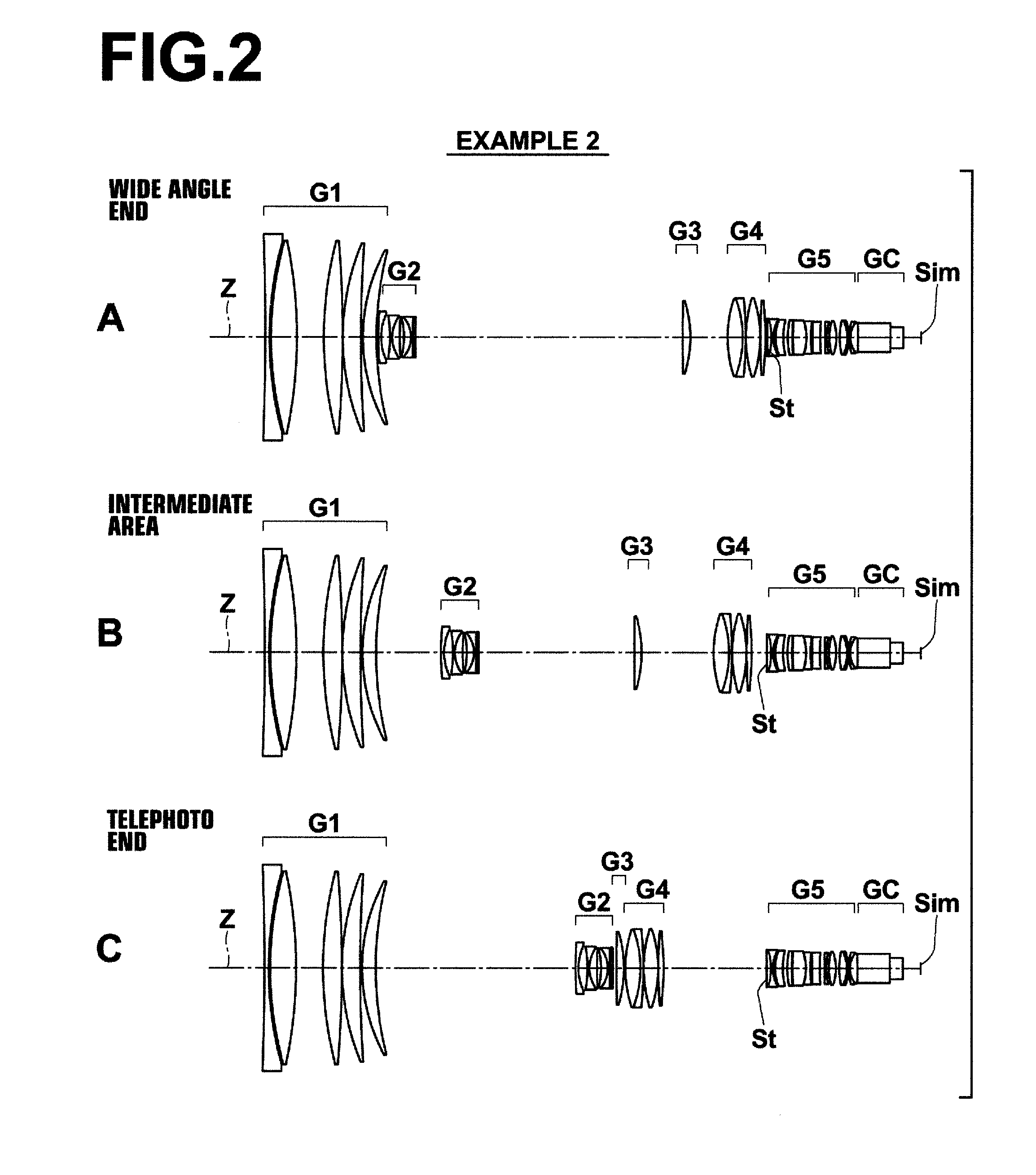
[0122]The cross sectional view of lenses in Example 2 is shown in FIG. 2, and detailed configurations thereof are shown in FIGS. 10 through 12. FIG. 10 shows the detailed configuration of the first lens group G1 and the second lens group G2, FIG. 11 shows the detailed configurations of the third lens group G3 and the fourth lens group G4, and FIG. 12 shows the detailed configuration from the fifth lens group G5 to the image formation surface Sim.

[0123]In Example 2, the first lens group G1 is of a five-lens configuration including lenses L1 through L5, the second lens group G2 is of a six-configuration including lenses L21 through L26, the third lens group G3 is of a one-lens configuration including L31, the fourth lens group G4 is of a four-lens configuration including lenses L41 through L44, and the fifth lens group G5 is of a twelve-lens configuration including an aperture stop St and lenses L51 through L62.

[0124]Lens data of the zoom lens according to Example 2 is shown in Table ...

example 3

[0125]The cross sectional view of lenses in Example 3 is shown in FIG. 3, and detailed configurations thereof are shown in FIGS. 13 through 15. FIG. 13 shows the detailed configuration of the first lens group G1 and the second lens group G2, FIG. 14 shows the detailed configurations of the third lens group G3 and the fourth lens group G4, and FIG. 15 shows the detailed configuration from the fifth lens group G5 to the image formation surface Sim.

[0126]In Example 3, the first lens group G1 is of a five-lens configuration including lenses L1 through L5, the second lens group G2 is of a six-lens configuration including lenses L21 through L26, the third lens group G3 is of a one-lens configuration including a lens L31, the fourth lens group G4 is of a four-lens configuration including lenses L41 through L44, and the fifth lens group G5 is of a thirteen-lens configuration including an aperture stop St and lenses L51 through L63.

[0127]Lens data of the zoom lens according to Example 3 is s...


PUM


Abstract

The zoom lens substantially consists of a positive first lens group fixed while changing magnification, a negative second lens group which moves from the object side to the image side while changing magnification, a positive third lens group which moves while changing magnification, and a positive fourth lens group which moves from the image side to the object side while changing magnification, and a positive fifth lens group fixed while changing magnification in this order from the object side. A floating system in which the third lens group and the fourth lens group move relative to each other while changing magnification is adopted. The image formation magnification rates of the combined lens group formed by the third lens group and the fourth lens group together and the second lens group simultaneously pass −1× point while changing magnification from the wide angle end to the telephoto end.

Description

CROSS-REFERENCE TO RELATED APPLICATIONS[0001]This application is a Continuation of PCT International Application No. PCT / JP2013 / 003334 filed on May 27, 2013, which claims priority under 35 U.S.C. §119(a) to Japanese Patent Application No. 2012-132860 filed on Jun. 12, 2012. Each of the above application(s) is hereby expressly incorporated by reference, in its entirety, into the present application.BACKGROUND OF THE INVENTION[0002]1. Technical Field[0003]The present invention relates to a zoom lens and an imaging apparatus, and particularly to a zoom lens having a high magnification ratio suitable for mounting onto TV cameras, video cameras, and the like and an imaging apparatus including this zoom lens.[0004]2. Description of the Related Art[0005]Conventionally, zoom lenses of a three-group configuration in which three groups move while changing magnification to have higher performance are known as the zoom lenses to be mounted onto a TV camera, a video camera, and the like (Patent ...

Claims


Application Information

Patent Timeline
IPC IPC(8): G02B15/173G02B13/18
CPCG02B13/18G02B15/173G02B13/0045G02B15/20G02B15/145129
Inventor IKEDA, SHINKICHIAOI, TOSHIHIRO
Owner FUJIFILM CORP
Why Eureka
Try Eureka