Smart Card Connection Circuit of Electronic Device and Electronic Device
- Summary
- Abstract
- Description
- Claims
- Application Information
AI Technical Summary
Benefits of technology
Problems solved by technology
Method used
Image


Examples
embodiment 1
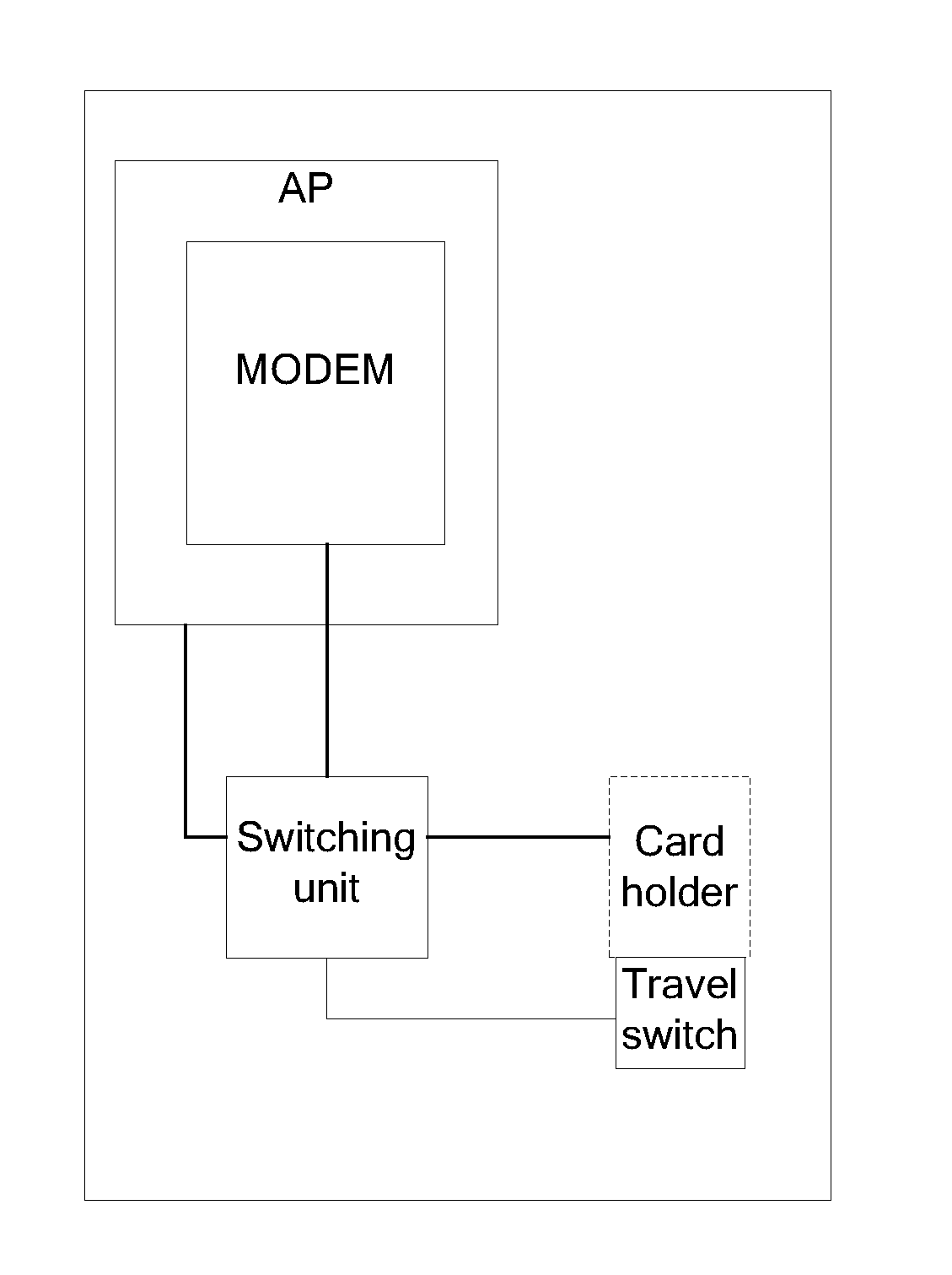
[0027]As shown in FIG. 1, a smart card connection circuit of an electronic device provided by this embodiment of the present invention may be applied to an electronic device such as a mobile phone or a tablet computer (pad). This embodiment is described by using a SIM card in a mobile phone as an example. The SIM card connection circuit includes a card holder, a travel switch, and a switching unit. The switching unit is equivalent to four synchronous single pole double throw switches, with an input end on the right side and two output ends on the left side, where a first output end is a modem of a mobile phone and a second output end is a ground terminal.
[0028]A power cable pin (VSIM) on the card holder and each signal cable pin (including a reset signal cable pin (RST), a clock signal cable pin (CLK) and a data cable pin (DAT)) are connected to corresponding interfaces at the input end of the switching unit, a contact of the travel switch is located in the card holder, and an outpu...
embodiment 2
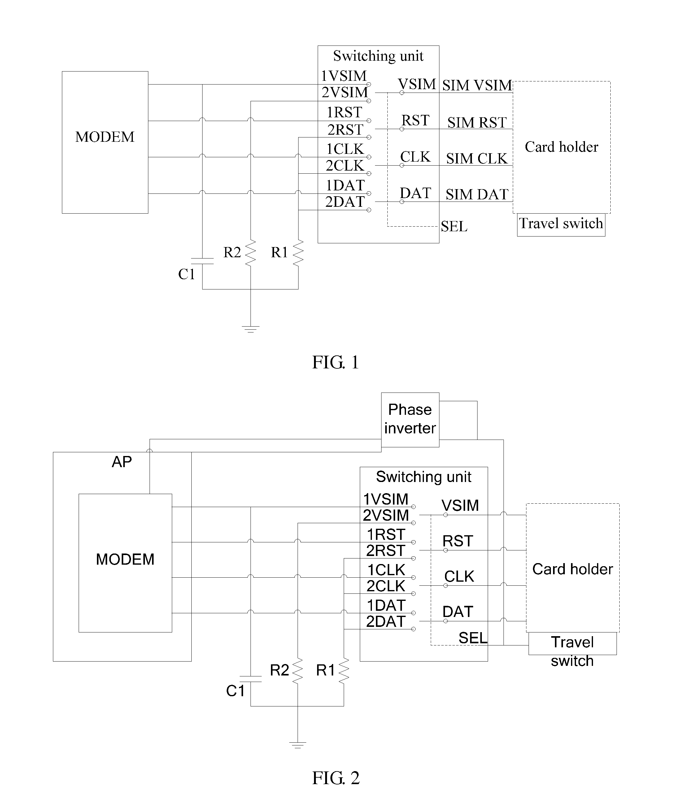
[0037]As shown in FIG. 2 and FIG. 3, in this embodiment, which is based on Embodiment 1, an output end of a travel switch is further connected to a general purpose input / output (GPIO) of a MODEM so that the MODEM can determine whether a SIM card is in position (a preset position in a card holder).
[0038]Further, the output end of the travel switch is further connected to a GPIO interface of an application processor (AP) of a mobile phone so that the AP can determine whether the SIM card is in position.
[0039]In addition, a correct power-on sequence of the SIM card is as follows. A power cable VSIM is powered on before each of signal cables CLK, RST, and DAT is powered on. When the SIM card is installed on the card holder and is located at the preset position, the SIM card touches a contact of the travel switch, and the AP of the mobile phone can detect, through the GPIO interface, that the SIM card is in position. Therefore, the AP can control a power cable of the SIM card to be power...
embodiment 3
[0046]As shown in FIG. 4, according to another aspect, the present invention further provides an electronic device, on which the smart card connection circuit according to either of the foregoing Embodiment 1 and Embodiment 2 is disposed. The electronic device may specifically be a mobile phone (a cell phone), which uses the smart card connection circuit to prevent a SIM card in the mobile phone from being burned out when the SIM card is detached from a card holder.
[0047]As shown in FIG. 4, the card holder in the mobile phone is configured to install the SIM card. Each contact sheet on the SIM card is connected to a switching unit by using the card holder and is further connected to a MODEM by using a first output end of the switching unit. When the SIM card leaves a preset position in the card holder, a travel switch controls the switching unit to switch to a second output end, and each signal cable pin on the card holder is grounded by using the switching unit first before a power...
PUM
 Abstract
Description
Claims
Application Information
PatSnap Eureka turns technology decisions into work you can execute. Powered by our Innovation Knowledge Graph, it runs expert workflows across engineering, life sciences, materials and intellectual property. Get your review-ready output in minutes.


