Snap Hook

a hook and snap technology, applied in the field of hooks, can solve problems such as damage to the conductor

Inactive Publication Date: 2015-04-09
BUCKINGHAM MFG
View PDF13 Cites 3 Cited by
  • Summary
  • Abstract
  • Description
  • Claims
  • Application Information

AI Technical Summary

Benefits of technology

[0010]It is another object and advantage of the present invention to provide a snap hook that more securely retains the gate to the main body when closed.
[0011]It is a further object and advantage of the present invention to provide a snap hook that includes a larger opening in order to engage larger objects.
[0012]Other objects and advantages of the present invention will in part be obvious and in part appear hereinafter.
[0013]In accordance with the foregoing objects and advantages, the present invention provides a snap hook essentially comprising a main body having an arcuate portion that transition between a spine and a gate latching end, wherein the interior edges of the arcuate portion are radiused. The snap-hook further comprises a gate that is pivotally attached to the main body, and a lock that pivotally mounts to the main body and in securing relation to the gate to prevent the gate from opening unless and until the lock is manually, pivotally moved by depressing on its end. The gate latching end of the main body includes a notch for receiving the end of the gate wherein the notch includes an inwardly directed upper, extension piece that will engage the end of the gate if it is inadvertently pushed towards an open position.

Problems solved by technology

When a load is applied, the edges of the arcuate portion will bite or cut into the conductor, potentially causing damage to the conductor.

Method used


Image

  • Snap Hook
  • Snap Hook
  • Snap Hook

Examples


Embodiment Construction

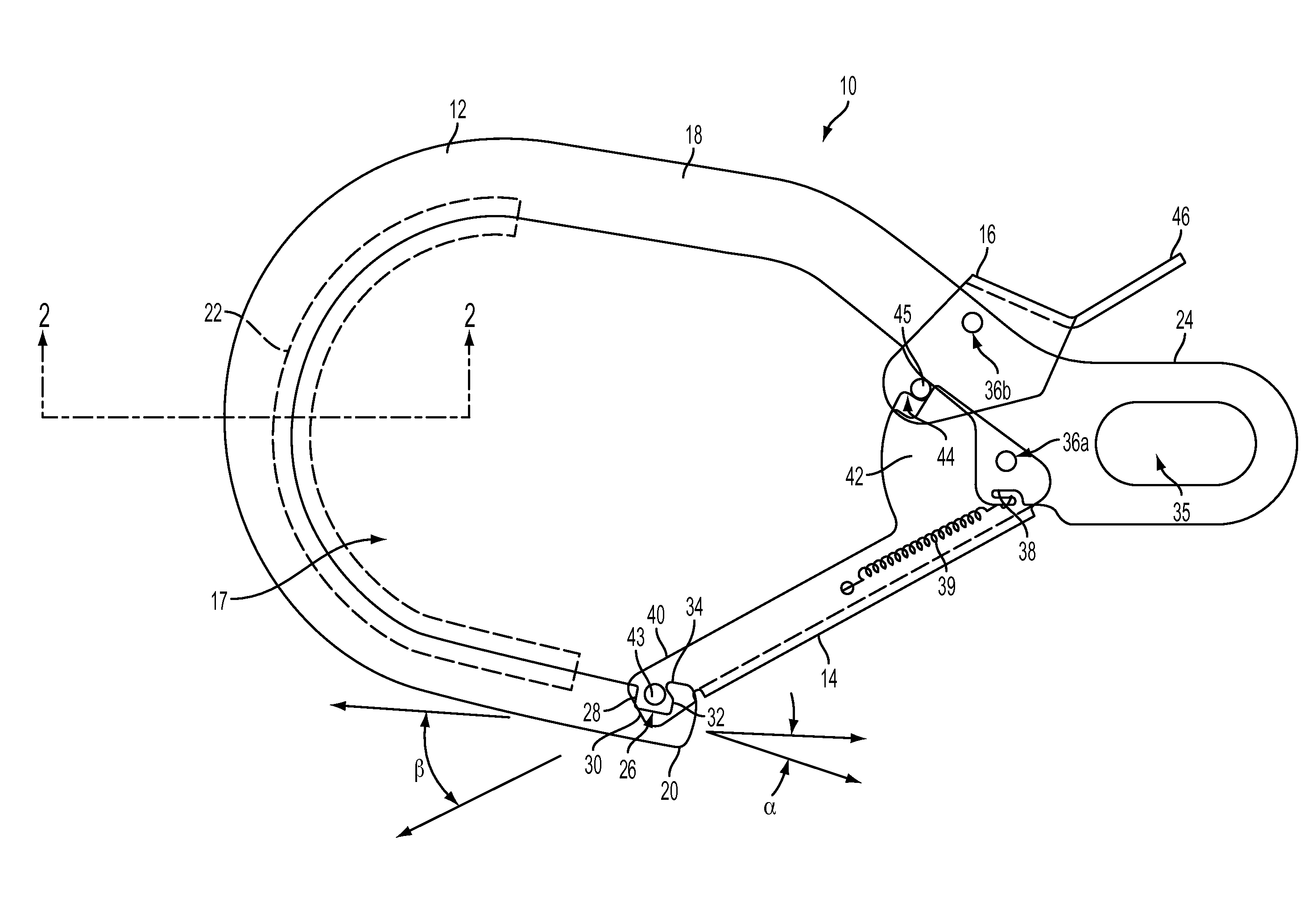
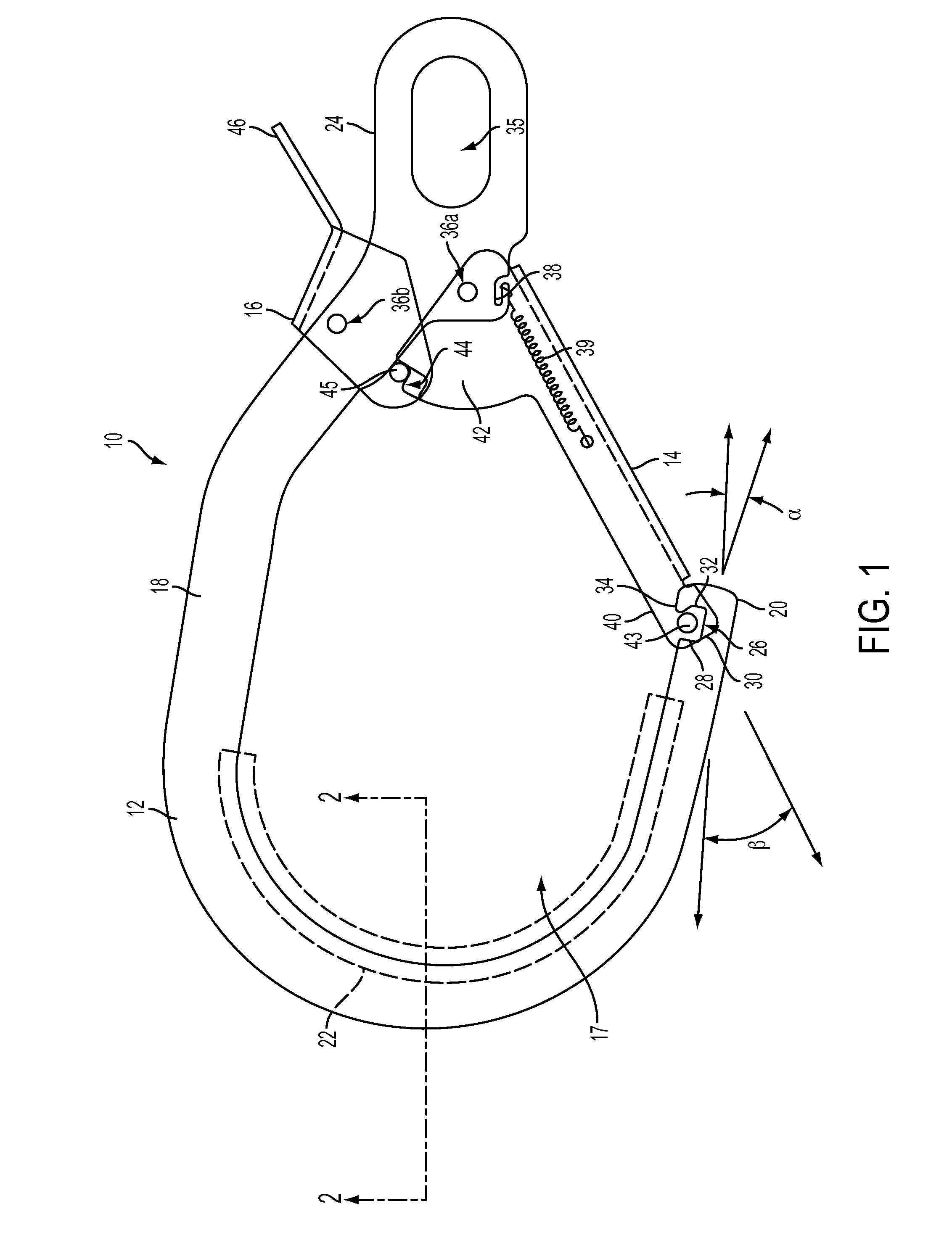
[0021]Referring now to the drawings, wherein like reference numerals refer to like parts throughout, there is seen in FIG. 1 a snap-hook designated generally by reference numeral 10. Snap-hook 10 comprises three principal components: a main body 12, a gate 14 pivotally mounted to main body 12, and a gate lock 16 pivotally attached to main body 12 for selective movement into and out of engagement with gate 14.

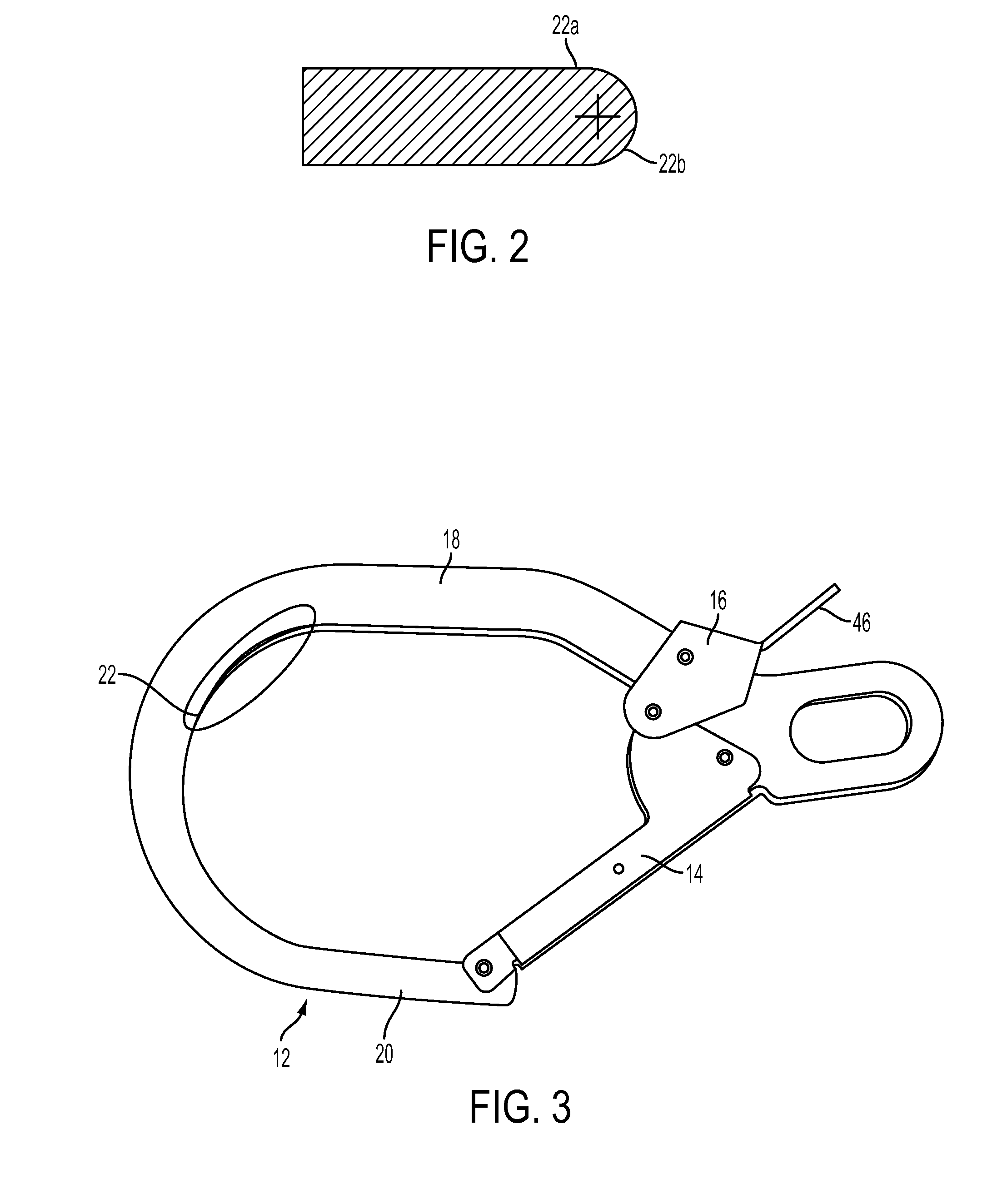
[0022]With regard to main body 12, it defines an oval opening 17 by way of a spine region 18, a gate engaging end 20, an arcuate region 22 that extends between spine region 18 and gate engaging end 20, and a mounting end 24 positioned at the terminal end of spine region 18. As shown in FIG. 2, the interior edges 22a and 22b of arcuate region 22 are radiused in order to remove any sharp edges that can cut or bite into a conductor to which snap-hook 10 may be attached.

[0023]The gate engaging end 20 of main body 12 comprises a notch 26 formed therein for receiving a terminal end of...


PUM


Abstract

A snap hook essentially including a main body having an arcuate portion that transition between a spine and a gate latching end, wherein the interior edges of the arcuate portion are radiused. The snap-hook further includes a gate that is pivotally attached to the main body, and a lock that pivotally mounts to the main body and in securing relation to the gate to prevent the gate from opening unless and until the lock is manually, pivotally moved by depressing on its end. The gate latching end of the main body includes a notch for receiving the end of the gate wherein the notch includes an inwardly directed upper, extension piece that will engage the end of the gate if it is inadvertently pushed towards an open position.

Description

REFERENCE TO RELATED APPLICATION[0001]The present application relates and claims priority to U.S. Provisional Patent Application Ser. No. 61 / 886,981, filed Oct. 4, 2013, the entirety of which is hereby incorporated by reference.BACKGROUND[0002]1. Field of Invention[0003]The present invention relates to hooks, and more particularly to snap hooks used by utility linemen.[0004]2. Background of Art[0005]Snap hooks used by utility linemen provide a safety mechanism when climbing poles and working on a utility line. The snap-hooks are used to tether a linemen or equipment to a conductor or angle iron that is attached to a pole / tower / other structure. In the event of a fall, the snap hook will prevent its load from falling farther than the length of the rope or lanyard used as the tether.[0006]Conventional snap-hooks comprise a main body with an oval opening, a spring loaded gate that pivotally mounts to the main body and permits the oval opening to become accessible or closed, and a lock t...

Claims


Application Information

Patent Timeline
Patent Type & Authority Applications(United States)
IPC IPC(8): A62B35/00F16B45/02
CPCF16B45/02A62B35/0075Y10T24/4453
Inventor CANFIELD, DEFOREST C.
Owner BUCKINGHAM MFG
Why Eureka
Try Eureka