
Dual-slope light guide, light source module and optical assembly for scanner

a technology of light guide and optical assembly, which is applied in the direction of fibre light guide, lighting and heating apparatus, instruments, etc., can solve the problems of inability to let the designer adjust the transversal light property of the light guide, the response curve of the image sensor cannot be satisfied, and the requirements are increasingly stringent or diversified

Active Publication Date: 2015-04-09
AVISION
View PDF4 Cites 3 Cited by
  • Summary
  • Abstract
  • Description
  • Claims
  • Application Information

AI Technical Summary

Benefits of technology

The present invention provides a dual-slope light guide and a light source module and optical assembly for a scanner. The dual sloped surfaces of the light guide are formed with triangular pyramidal or columnar chambers or entities to serve as the reflecting structures. This design allows the adjustment of the light emitting property and the light beam luminance curve of the light source module by adjusting the parameters of the dual sloped surfaces and the triangular pyramidal or columnar chambers or entities. This results in the ability to finely and gradually change the light source, which improves the quality of the scan and eliminates straight-line images or nonuniform phenomena.

Problems solved by technology

This transversally extended and longitudinally arranged V-shaped grooves only can let the designer adjust the longitudinal light property of the light guide, but cannot let the designer adjust the transversal light property of the light guide.
Thus, the increasingly stringent requirements or the diversified requirements, such as the response curve of the image sensor, cannot be satisfied.

Method used


Image

  • Dual-slope light guide, light source module and optical assembly for scanner
  • Dual-slope light guide, light source module and optical assembly for scanner
  • Dual-slope light guide, light source module and optical assembly for scanner

Examples


first embodiment

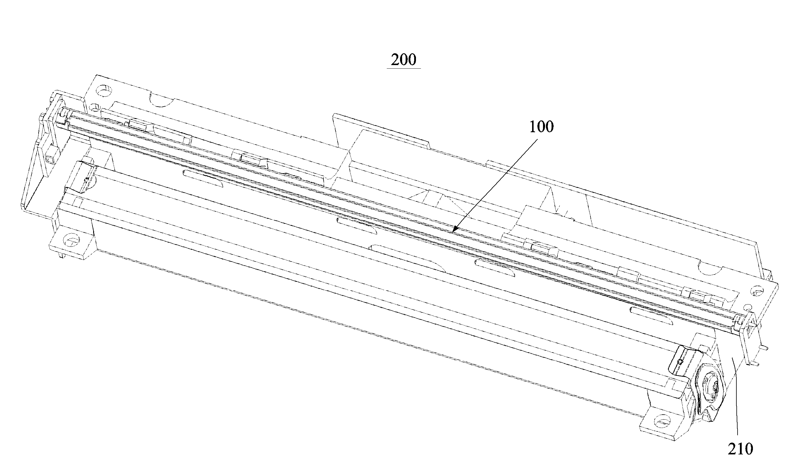
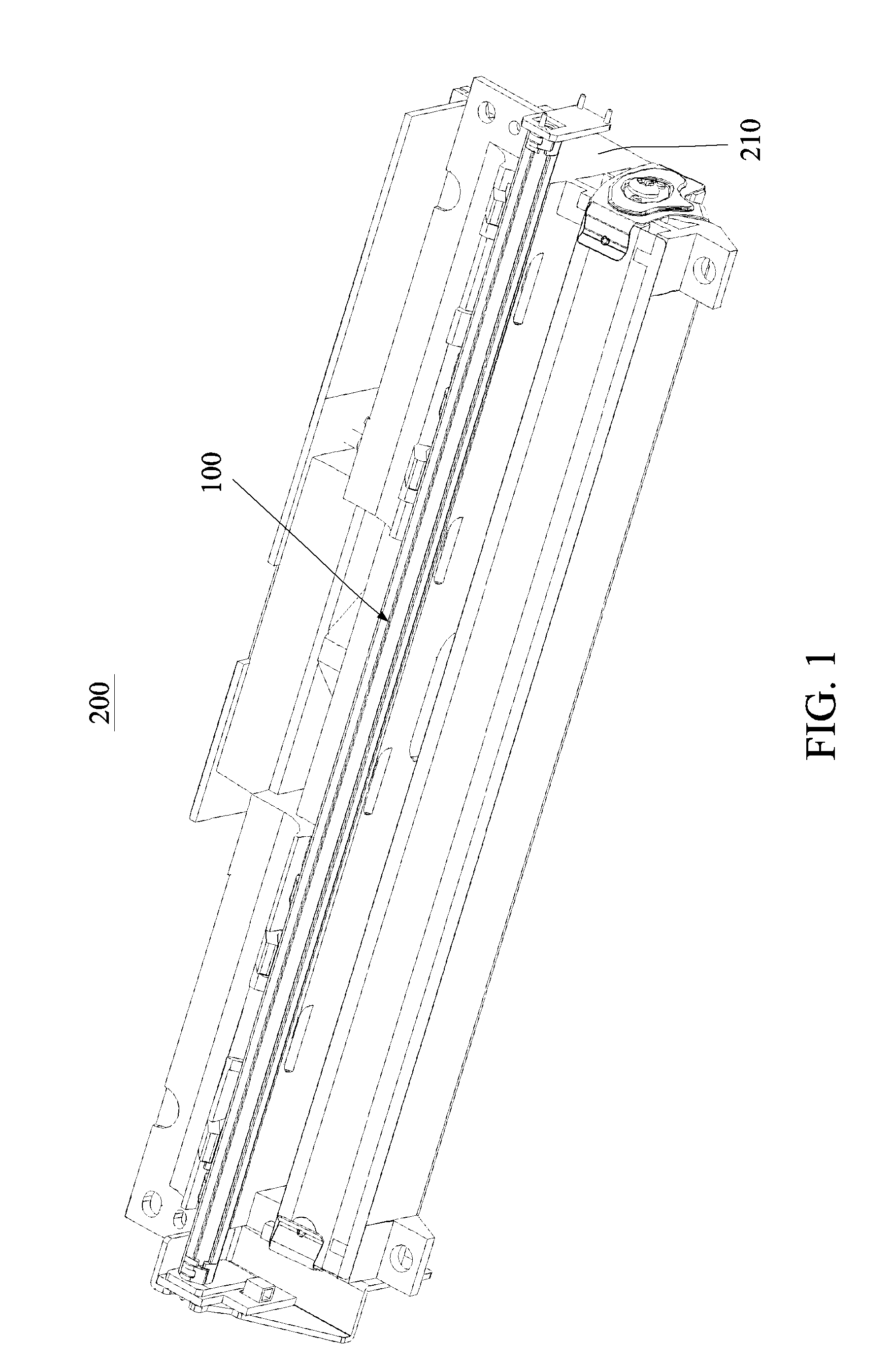
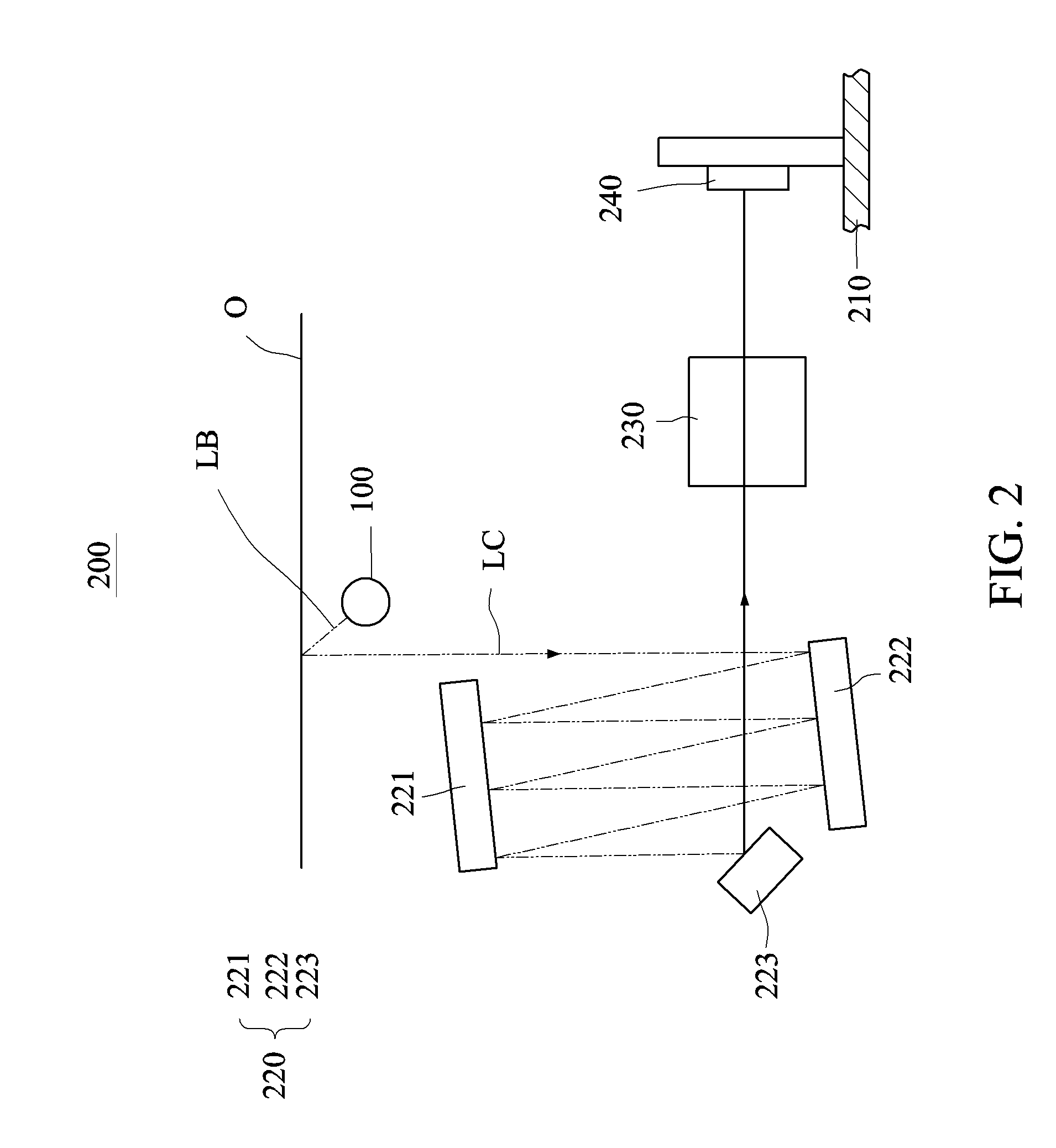
[0026]FIG. 1 shows a pictorial view of an optical assembly 200 according to the present invention. FIG. 2 shows a schematic view of an arrangement of the optical assembly 200 of FIG. 1. Referring to FIGS. 1 and 2, the optical assembly 200 of this embodiment comprises a housing 210, a light source module 100, a reflecting mirror module 220, a lens 230 and an image sensor 240.

[0027]The light source module 100, mounted on the housing 210, provides linear light LB. The reflecting mirror module 220, the lens 230 and the image sensor 240 are disposed in the housing 210. In this embodiment, the reflecting mirror module 220 including three reflecting mirrors 221, 222 and 223 will be described as an example, which does not intend to restrict the present invention thereto, wherein the number of the reflecting mirrors may be increased or decreased properly, or even a single reflecting mirror may be used to implement this invention. The light source module 100 illuminates the linear light LB on...

third embodiment

[0038]FIG. 10 shows a side view of a light guide 1″ according to the present invention. FIG. 11 shows a pictorial view of the reflecting structure 12″ / 22″ of FIG. 10. As shown in FIGS. 10 and 11, the V-shaped structure of each of the first reflecting structures 12″ and the second reflecting structures 22″ defines a triangle columnar entity. The triangle columnar entity has the high structural strength and the low manufacturing cost when the required specification of the linear light LB is satisfied.

[0039]FIG. 12 shows a side view of a light guide 1′″ according to a fourth embodiment of the present invention. As shown in FIG. 12, this embodiment is similar to the third embodiment except that the V-shaped structure of each of the first reflecting structures 12′″ and the second reflecting structures 22′″ defines a triangle columnar chamber (no detailed structure is depicted because the chamber is similar to the entity of FIG. 10). The triangle columnar chamber has the high structural s...


PUM


Abstract

A dual-slope light guide includes a first surface, a second surface and a curved surface. The first surface has first reflecting structures. The second surface, connected to the first surface, has second reflecting structures. An included angle between the first surface and the second surface is unequal to 180 degrees. The curved surface connects the first surface to the second surface. The first surface, the second surface and the curved surface extend from a first end of the light guide to a second end of the light guide. A light beam incident to the first end of the light guide is reflected and converted by the first reflecting structure and the second reflecting structure into linear light emitted from the curved surface. A light source module and an optical assembly for a scanner are also disclosed.

Description

[0001]This application claims priority of No. 102136434 filed in Taiwan R.O.C. on Oct. 9, 2013 under 35 USC 119, the entire content of which is hereby incorporated by reference.BACKGROUND OF THE INVENTION[0002]1. Field of the Invention[0003]The present invention relates to a dual-slope light guide and a light source module and an optical assembly for a scanner, and more particularly to a light guide having a dual-slope reflecting surface, and a light source module and an optical assembly, using the light guide, for a scanner.[0004]2. Related Art[0005]Light-emitting diodes (LED) have the advantages of the high energy conversion efficiency, the power-saving property, the long lifetime and the small size, and have been widely applied to various light sources. For a scanner, a light beam emitted from the LED is point light, which needs to be converted by a light guide into linear light so that the illumination light beam required to scan an original can be provided.[0006]The typical lig...

Claims


Application Information

Patent Timeline
IPC IPC(8): H04N1/028F21V8/00
CPCH04N1/02895G02B6/0088H04N2201/02497H04N1/0288G02B6/0091G02B6/0035G02B6/001G02B6/0038
Inventor SHIUE, SHIN GWOCHENG, SUNG-PO
Owner AVISION
Learn More