
Antiseptic applicator

Active Publication Date: 2015-04-09
CAREFUSION 2200 INC
View PDF3 Cites 5 Cited by
  • Summary
  • Abstract
  • Description
  • Claims
  • Application Information

AI Technical Summary

Benefits of technology

The patent describes an applicator assembly with various configurations. The invention can be modified in different ways without affecting the main idea. The patent is meant to be a guide and not a restriction.

Problems solved by technology

However, in the above-listed applicators, once the fluid is released from the container, there is no mechanism to control the flow of antiseptic solution to the surface (e.g., skin of a patient).

Method used


Image

  • Antiseptic applicator
  • Antiseptic applicator
  • Antiseptic applicator

Examples


Embodiment Construction

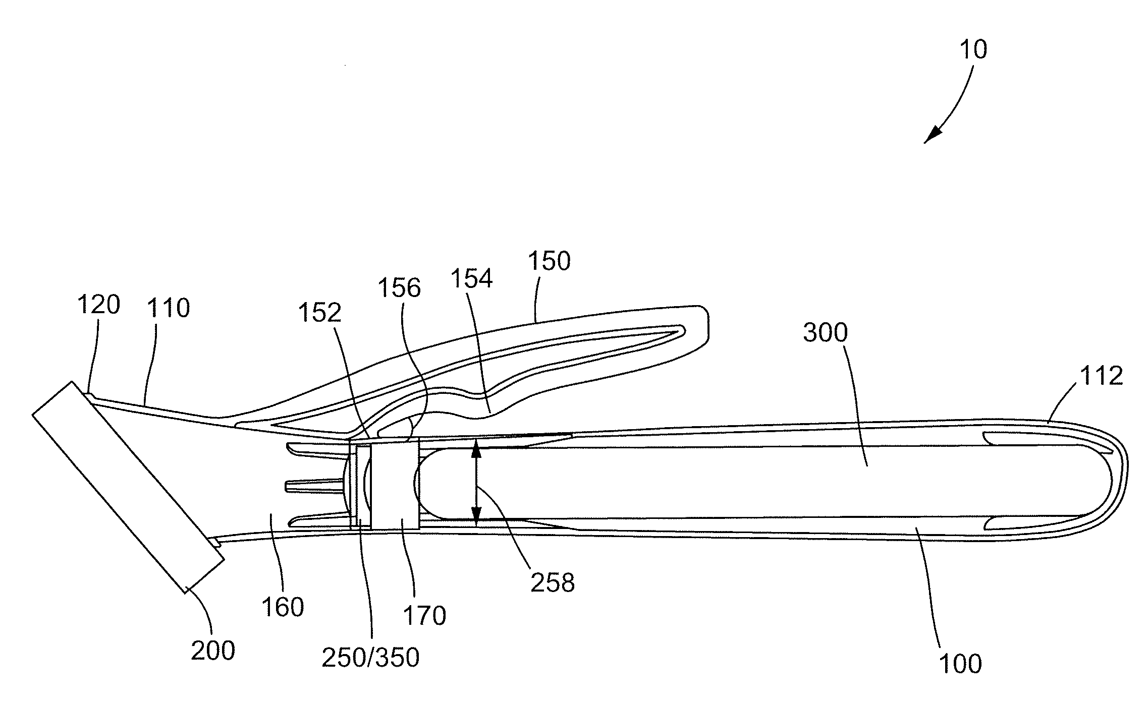
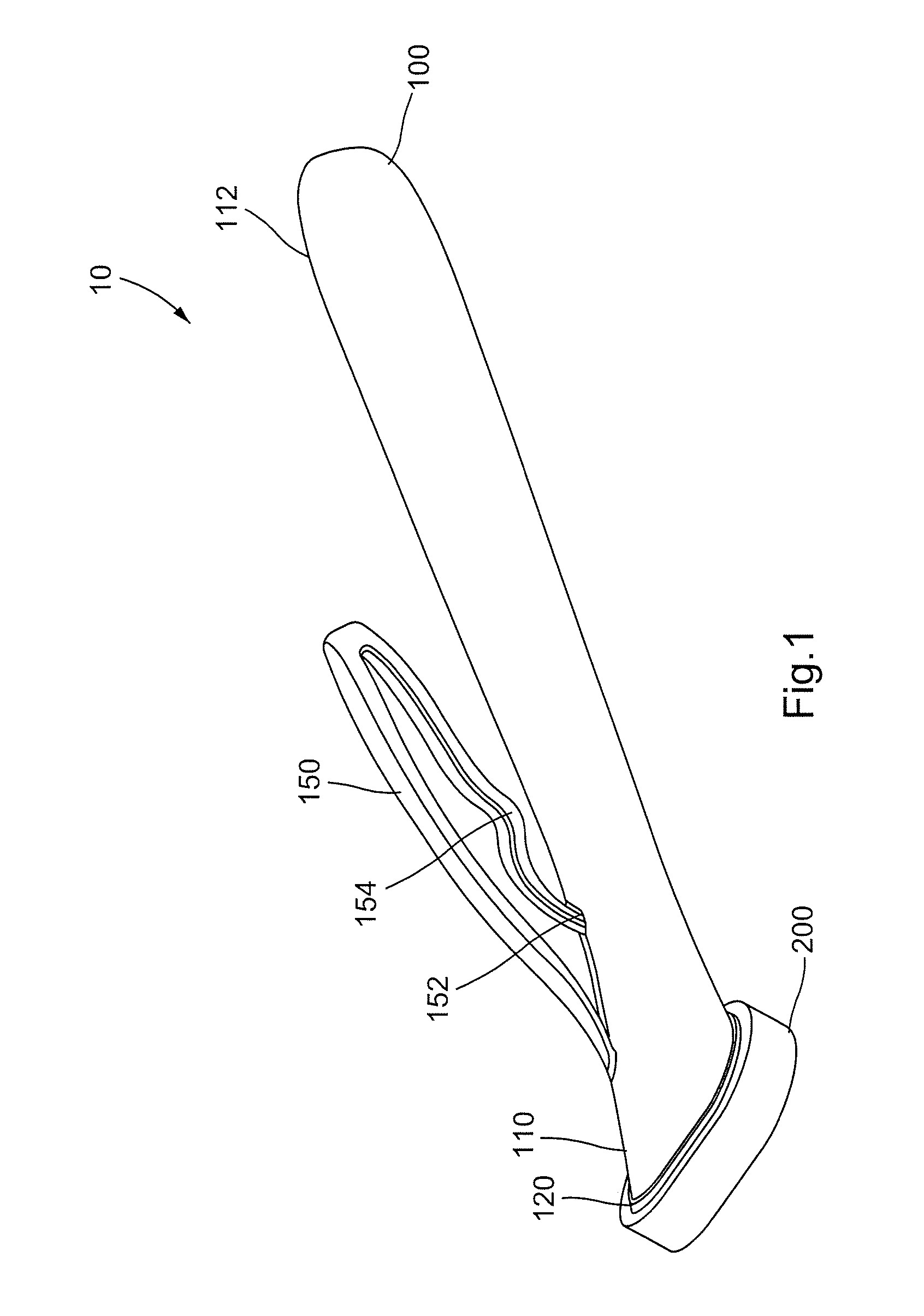
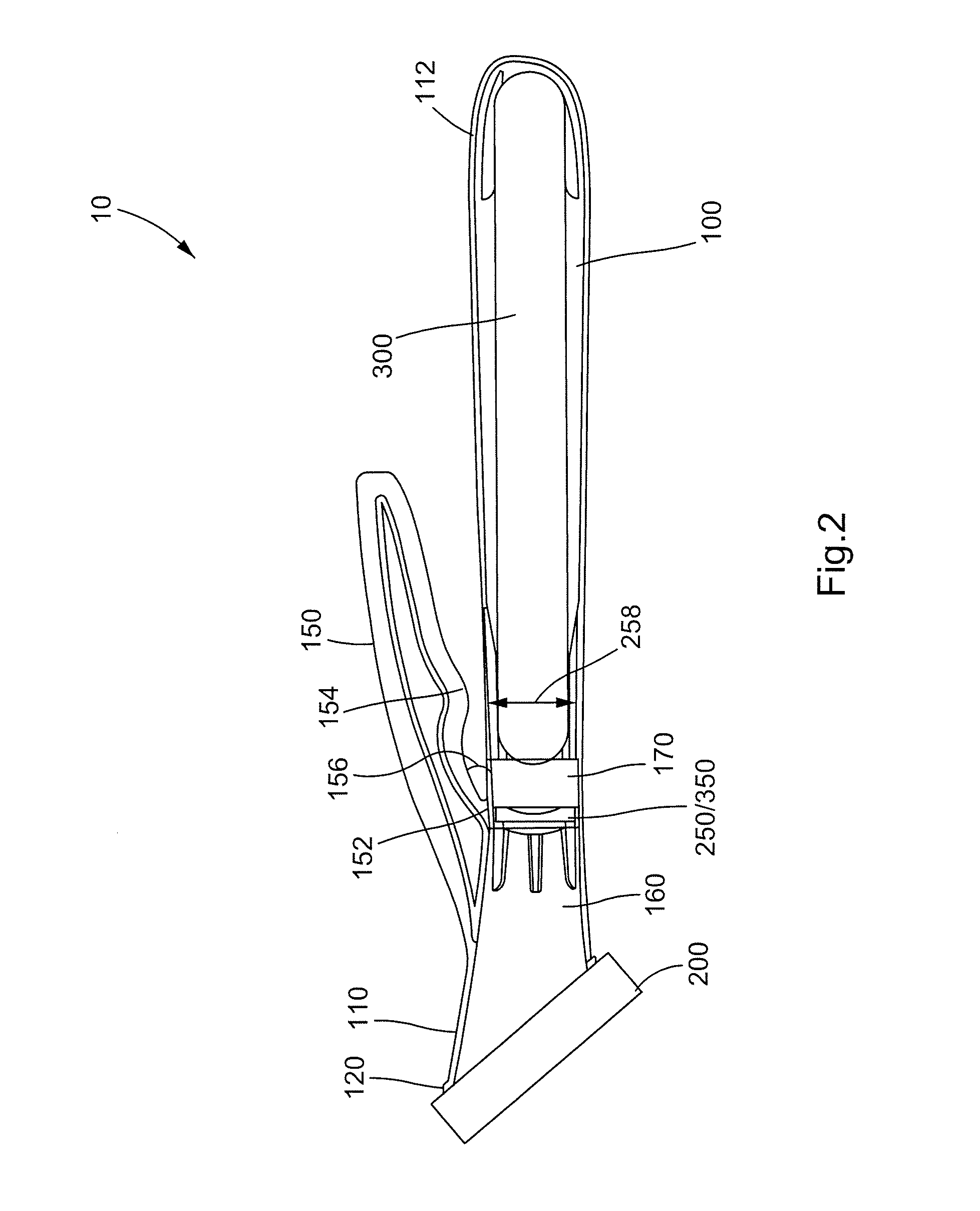
[0017]Various aspects of an antiseptic applicator may be illustrated by describing components that are coupled, attached, and / or joined together. As used herein, the terms “coupled”, “attached”, and / or “joined” are used to indicate either a direct connection between two components or, where appropriate, an indirect connection to one another through intervening or intermediate components. In contrast, when a component is referred to as being “directly coupled”, “directly attached”, and / or “directly joined” to another component, there are no intervening elements present.

[0018]Relative terms such as “lower” or “bottom” and “upper” or “top” may be used herein to describe one element's relationship to another element illustrated in the drawings. It will be understood that relative terms are intended to encompass different orientations of an antiseptic applicator in addition to the orientation depicted in the drawings. By way of example, if an antiseptic applicator in the drawings is turn...


PUM


Abstract

An applicator assembly may include a body having a proximal end portion and a distal end portion, an actuator operatively coupled to the body, a container disposed within the body, an application member attached to the distal end portion, and a valve disposed between the container and the application member. Actuation of the actuator opens the valve and places the interior of the container in fluid communication with the application member by way of a compressive force applied to the body. A method of applying a solution to a surface may include actuating the actuator, wherein actuation of the actuator applies a compressive force to the body that opens the valve and places the interior of the container in fluid communication with the application member, and contacting the application member to the surface, thereby applying the solution to the surface.

Description

BACKGROUND[0001]1. Field[0002]The present disclosure relates to an antiseptic applicator and method of use thereof, and more particularly, to an antiseptic applicator that uses a compressive force to actuate release of a sealed solution, preferably an antimicrobial solution, from a container.[0003]2. Description of Related Art[0004]Antiseptic applicators for the preparation of a patient prior to surgery, for example, are known and common in the prior art. Conventional applicators rely on various means of actuation to release a self-contained reservoir of antimicrobial solution for sterilization of the patient's skin. For example, a number of applicators are designed with a puncturing means. These applicators typically include a head with a spike, for example, and a sealed container or cartridge. A push or screw motion is employed to axially translate the head toward the sealed container so that the spike may pierce the sealed container and effectuate the release of the solution cont...

Claims


Application Information

Patent Timeline
IPC IPC(8): A61F13/40A61L2/18
CPCA61L2/18A61M35/006
Inventor DEGALA, SATISHTHURMOND, II, KENNETH BRUCEDOKKEN, KENNETH MICHAELVAIDYANATHAN, AISHWARYAMAGALLON, ANGELPARROTT, DAVID A.KRUPP, BENJAMIN T.
Owner CAREFUSION 2200 INC
Learn More