
Intelligent reamer for rotary/sliding drilling system and method

a technology of intelligent reamer and rotating/sliding drilling, which is applied in the field of intelligent reamer controllers in the borehole, can solve the problems of unsuitability, slow opening and closing, and/or inability to meet the purpose, and achieve the effect of improving drilling speed, improving borehole quality, and responding quickly

Active Publication Date: 2015-04-16
IREAMER LLC
View PDF3 Cites 54 Cited by
  • Summary
  • Abstract
  • Description
  • Claims
  • Application Information

AI Technical Summary

Benefits of technology

The invention provides an improved reamer that works well with both sliding drilling and rotating drilling, using a mud motor. The electronic control unit can also be programmed to prevent unintended reamer action by allowing the control to stay in a closed position.

Problems solved by technology

Due to frequently alternating changes in types of drilling, prior art expandable reamers have significant disadvantages when used for rotating / sliding directional steering operations making them unsuitable, slow to open and close, and / or incapable for this purpose.
However, due to the need for pumping drilling fluid during the sliding directional drilling, if the reamer expands due solely to drilling fluid flow this can be very problematic.
The time required for the ball to reach the reamer results in significant lost rig time, making this type of expandable reamer unsuitable for rotating / sliding drilling operations with mud motors.
Even if this type of device can be repeatedly closed for sliding drilling, which is not normally the case, this type of activation is not well suited to switching quickly between sliding drilling and rotary drilling.
Dropping balls to close the reamer for sliding drilling is not realistically practical due to extensive lost rig time.
However, the variations in fluid flow or pressure, which is required to expand or retract the reamer members are time consuming to operate when switching frequently between rotary drilling and sliding drilling.
Reducing the flow rate may also adversely affect the performance of the drive system.
In addition, repeated flow reductions will significantly increase time lost due to switching and may be prone to both personnel and mechanical operation errors with frequent switching.
Repeated downlinking; however, result in significant time lost in switching the reamer members between an expanded or retracted.

Method used


Image

  • Intelligent reamer for rotary/sliding drilling system and method
  • Intelligent reamer for rotary/sliding drilling system and method
  • Intelligent reamer for rotary/sliding drilling system and method

Examples


Embodiment Construction

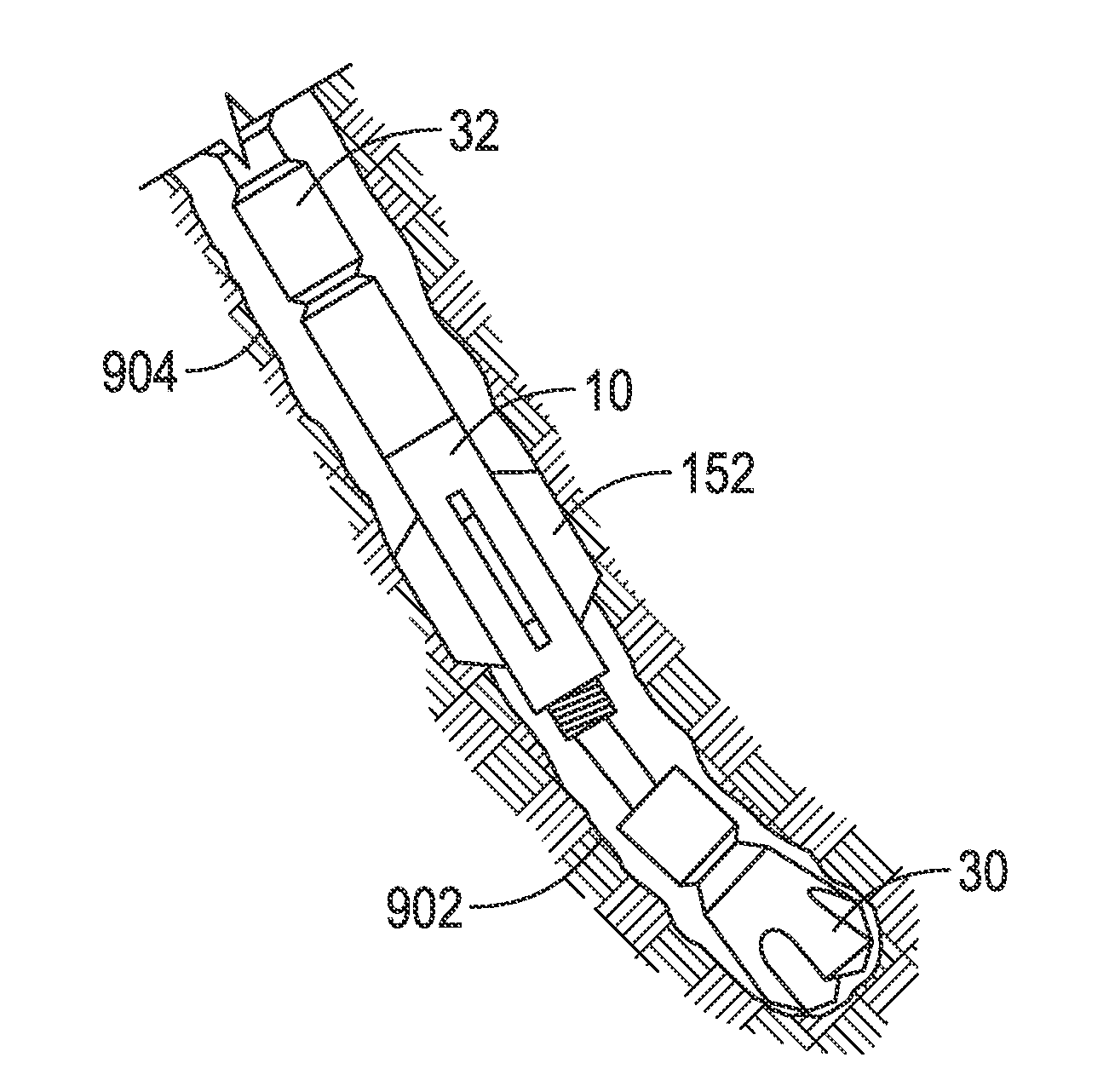
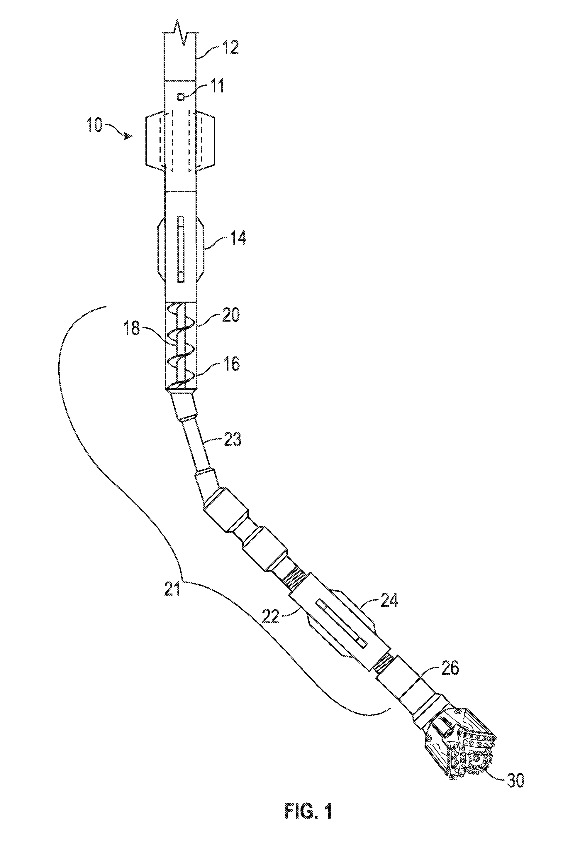
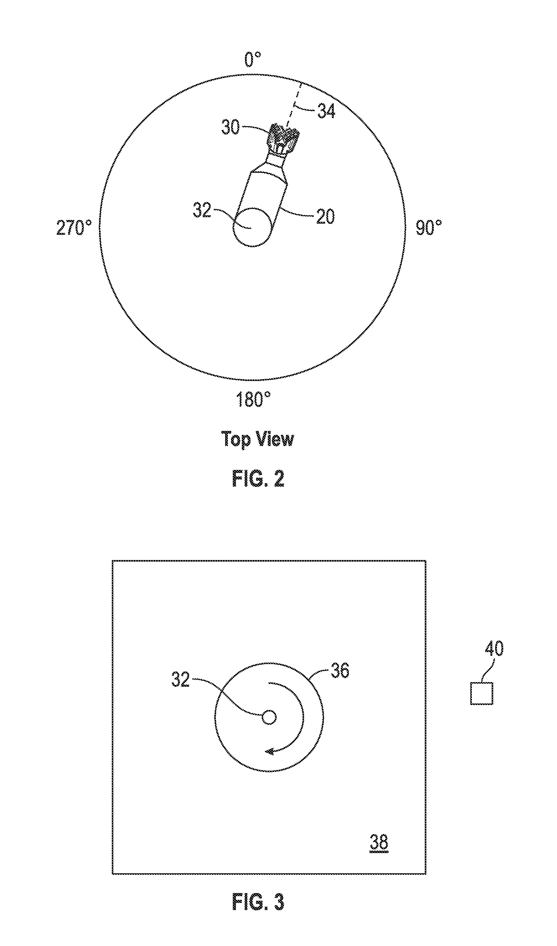
[0091]Turning now to the drawings, and more particularly FIG. 1, there is depicted a schematic elevational view of a downhole bottom hole assembly in accord with one possible non-limiting embodiment of the present invention.

[0092]In general overview of the drawings, it will be understood that such terms as “up,”“down,”“vertical,” and the like, are made with reference to the drawings and / or the earth and that the devices may not be arranged in such positions at all times depending on variations in operation, transportation, mounting, and the like. As well, the drawings are intended to describe the concepts of the invention so that the presently preferred embodiments of the invention will be plainly disclosed to one of skill in the art but are not intended to be manufacturing level drawings or renditions of final products and may include highly simplified conceptual views and exaggerated angles, sizes, and the like, as desired for easier and quicker understanding or explanation of the...


PUM


Abstract

A downhole intelligent reamer controller detects the difference between rotary drilling and sliding drilling, responds appropriately and quickly to multiple changes between rotary drilling and sliding drilling that may occur several times each stand of pipe. Additional controls prevent deployment of reamer members at inappropriate times such as when drilling out cement, testing, and running in and out of the wellbore. In one embodiment, a separate modular control sub is disclosed that may be utilized with and / or removably secured to an expandable reamer and / or other types of downhole tools.

Description

BACKGROUND OF THE INVENTION[0001]1. Field of the Invention[0002]The present invention relates generally to borehole reamers to enlarge the size of drilled borehole and, more particularly in some non-limiting embodiments, to a downhole intelligent reamer controller that can detect the difference between rotary drilling and sliding drilling, respond appropriately and quickly to multiple changes between rotary drilling and sliding drilling that may occur several times each stand of pipe, with additional controls to prevent deployment of reamer members at inappropriate times such as when drilling out cement, testing, and running in and out of the wellbore.[0003]2. Background of the Invention[0004]Expandable reamers or underreamers are well known in the oilfield drilling industry. The term reamer and underreamer is used herein interchangeably although often a reamer is considered to be a fixed blade device that may be the same or approximately the same size as the bit size.[0005]It is of...

Claims


Application Information

Patent Timeline
Patent Type & Authority Applications(United States)
IPC IPC(8): E21B7/00E21B44/06E21B47/00
CPCE21B7/00E21B47/00E21B44/06E21B10/32E21B44/00
Inventor MAY, MARK
Owner IREAMER LLC
Learn More