Rotary ground auger base and stand for supporting decoys and sporting equipment

a technology of auger base and stand, which is applied in the direction of machine supports, other domestic objects, mechanical equipment, etc., can solve the problem of decoy spinning around

Active Publication Date: 2015-04-23
DECOY STAKE SOLUTIONS LLC
View PDF7 Cites 8 Cited by
  • Summary
  • Abstract
  • Description
  • Claims
  • Application Information

AI Technical Summary

Benefits of technology

[0010]It is an object of this invention to provide a rotary ground auger base and stand with a helical coil at one end and a crank handle wh

Problems solved by technology

Some decoy stands have one or more spikes which are hammered into the ground with a hammer, rock, limb, or other tool; however, problems occur due to the in

Method used


Image

  • Rotary ground auger base and stand for supporting decoys and sporting equipment
  • Rotary ground auger base and stand for supporting decoys and sporting equipment
  • Rotary ground auger base and stand for supporting decoys and sporting equipment

Examples


Embodiment Construction

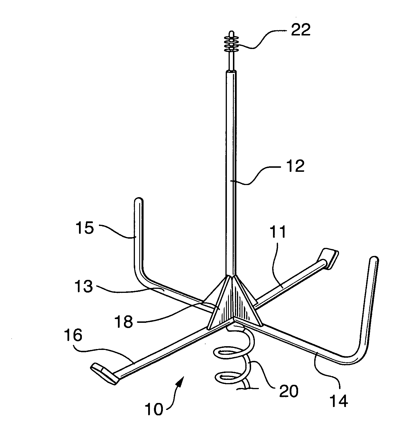
[0023]In accordance with the present invention, there is provided a rotary ground auger base and stand 10 for holding a device or adapter in a raised position above the ground for the intended use.

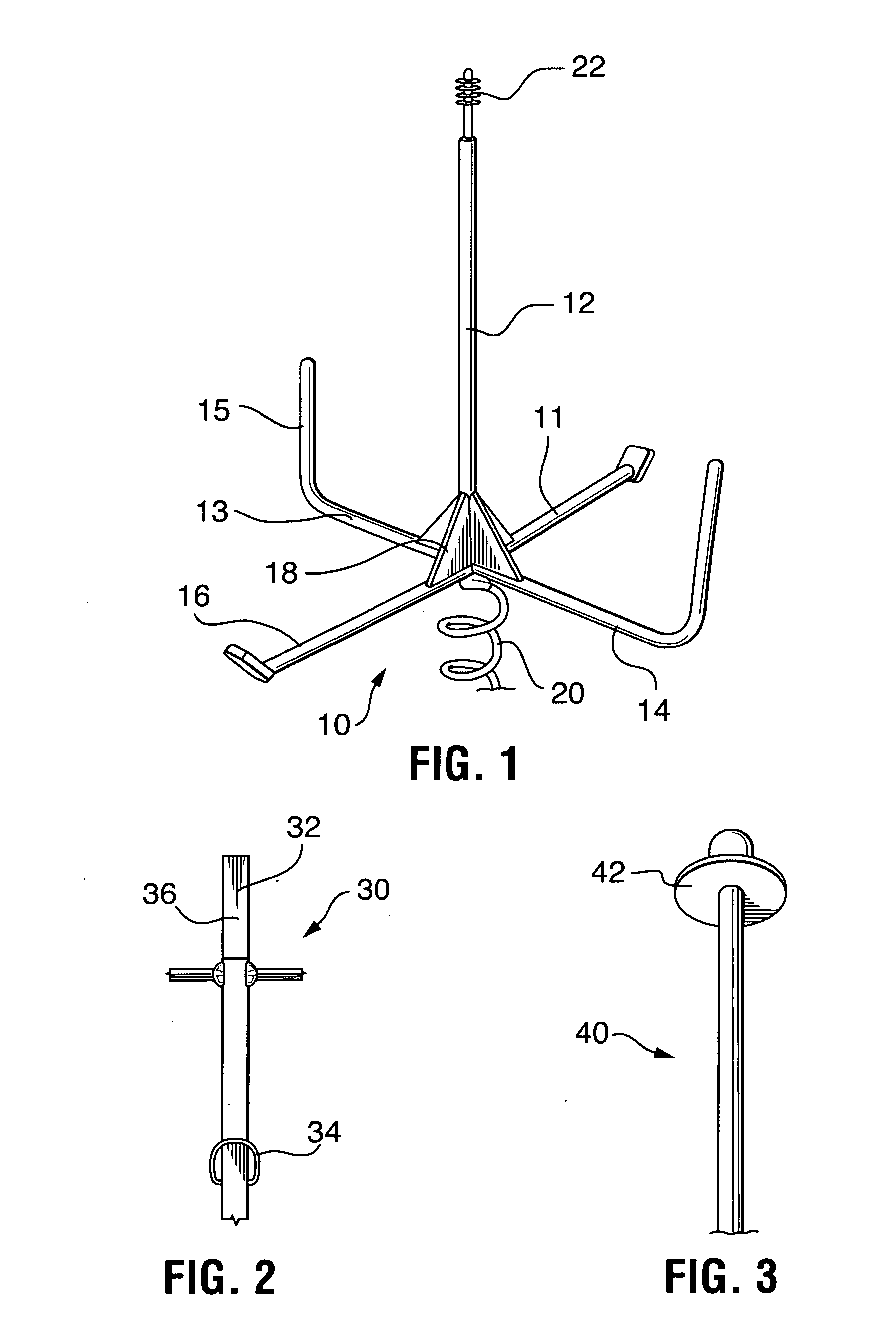
[0024]As shown in FIG. 1, the rotary ground auger base and stand 10 comprises or consists of a base having legs extending therefrom. An elongated shaft 12 with a threaded distal top end 22 at the top extends from a vertical rod or shaft extending from the base which sets on the ground. An auger comprising a helical coil 20 extends from the bottom of the base and includes spaced apart opposing laterally extending legs 11, 13, 14 and 16 for providing additional lateral support by bracing the stand against the ground. Legs 13 and 14 are opposite one another as are legs 11 and 16.

[0025]Legs 13 and 14 have upward extending arms 15 which are used as hand cranks to screw the helical coil 20 into the ground until the legs are in contact with the ground. As an option, the legs are braced against ro...


PUM


Abstract

A rotary mounting stand for removably holding a decoy, camera or there selected device upright on the ground. The stand includes an upright rod with a helical coil or flights forming an auger having a point at the lower distal end to be fixedly and removably screwed into the ground to support the stand in an upright position. The top end of the rod forming the stand shape cap configured, sized and shaped to correspond to the mounting base of a selected device to be supported on the stand. Just above the helical coil at least two outward extending legs extend normal to or perpendicular to the vertical rod forming a base when the auger portion is screwed into the ground.
The distal end of each of the legs are bent or angled to extend upward perpendicular from the ground a selected distance forming handles for the purpose of rotating the auger into the ground. The auger is intended to be cranked until the at least two outward extending legs come to bear against the ground for increased lateral support.

Description

CROSS REFERENCES TO RELATED APPLICATIONS[0001]This application is a continuation in part of U.S. application Ser. No. 13 / 998,981 filed on Dec. 30, 2013 and claims priority from U.S. Provisional Application Ser. No. 61 / 960,068 filed on Sep. 9, 2013 and U.S. Provisional Application Ser. No. 61 / 848,248 filed on Dec. 29, 2012 and U.S. Provisional Application Ser. No. 61 / 848,252 filed on Dec. 29, 2012 and U.S. Provisional Application Ser. No. 61 / 848,253 filed on Dec. 29, 2012 and U.S. Provisional Application Ser. No. 61 / 855,583 filed on May 28, 2013 all of which are incorporated by reference herein in their entirety.TECHNICAL FIELD[0002]The present invention relates to the field of mobile decoy stands.BACKGROUND OF THE INVENTION[0003]Duck, turkey, geese and other water fowl hunters often use decoys for attracting the fowl during hunting season. The decoys are typically displayed near or in the water and many are animated, that is, many decoys are provided with movable wings and heads whi...

Claims


Application Information

Patent Timeline
IPC IPC(8): E04H12/22A01M99/00A01M31/06
CPCE04H12/2223A01M99/00A01M31/06F16M11/041F16M11/28F16M13/022F16M2200/08F16M11/242F41B5/1453F41J1/10
Inventor BROOKS, KEVIN
Owner DECOY STAKE SOLUTIONS LLC
Why Eureka
Try Eureka