Induction heating cooking device

a technology of induction heating and cooking device, which is applied in the direction of ohmic resistance heating, climate sustainability, sustainable buildings, etc., can solve the problems that the product performance based on the design cannot be obtained, and achieve the effect of reducing the number of components, and constant distan

Active Publication Date: 2015-04-30
PANASONIC INTELLECTUAL PROPERTY MANAGEMENT CO LTD
View PDF2 Cites 21 Cited by
  • Summary
  • Abstract
  • Description
  • Claims
  • Application Information

AI Technical Summary

Benefits of technology

[0027]The induction heating cooking device according to the present disclosure can avoid stress attributable to pressing force applied from the heating coil unit to the top plate, can maintain a constant distance between the top plate and the heating coil, and can achieve simplification of a configuration by reducing the number of components and thinning the main body as well as improving easiness of assembling the main body.

Problems solved by technology

As a result, product performance based on the design cannot be obtained.

Method used


Image

  • Induction heating cooking device
  • Induction heating cooking device
  • Induction heating cooking device

Examples


first embodiment

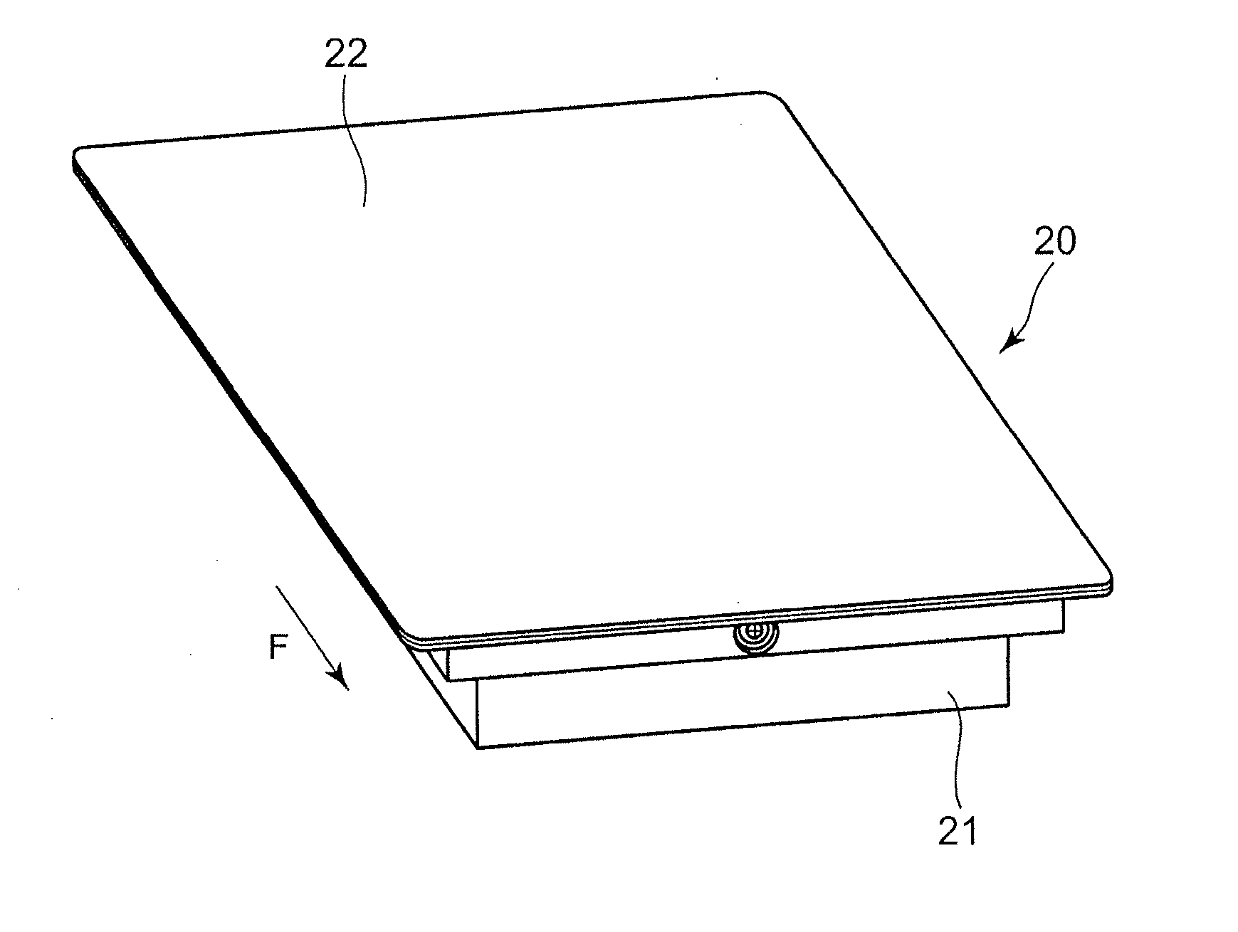
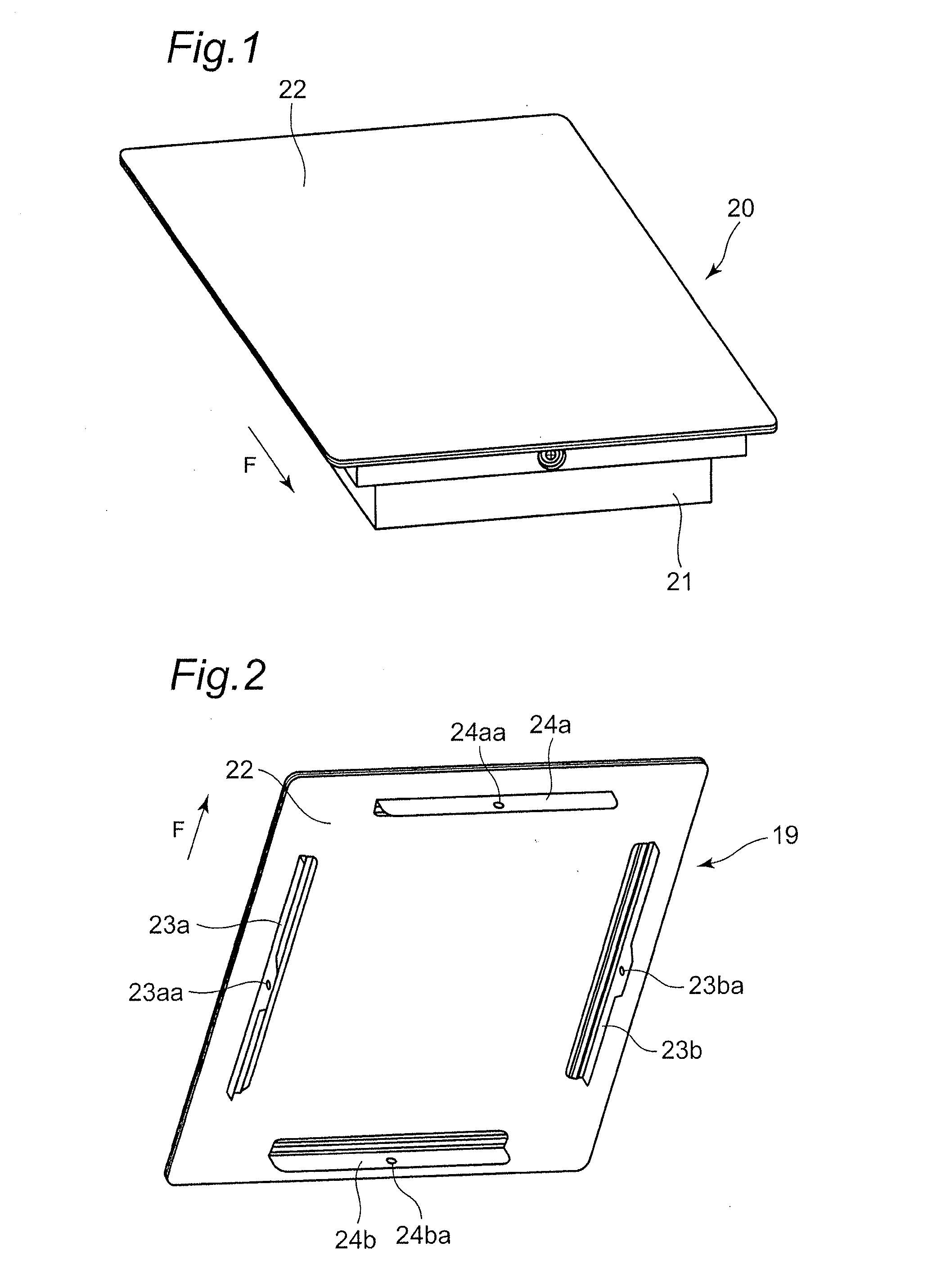
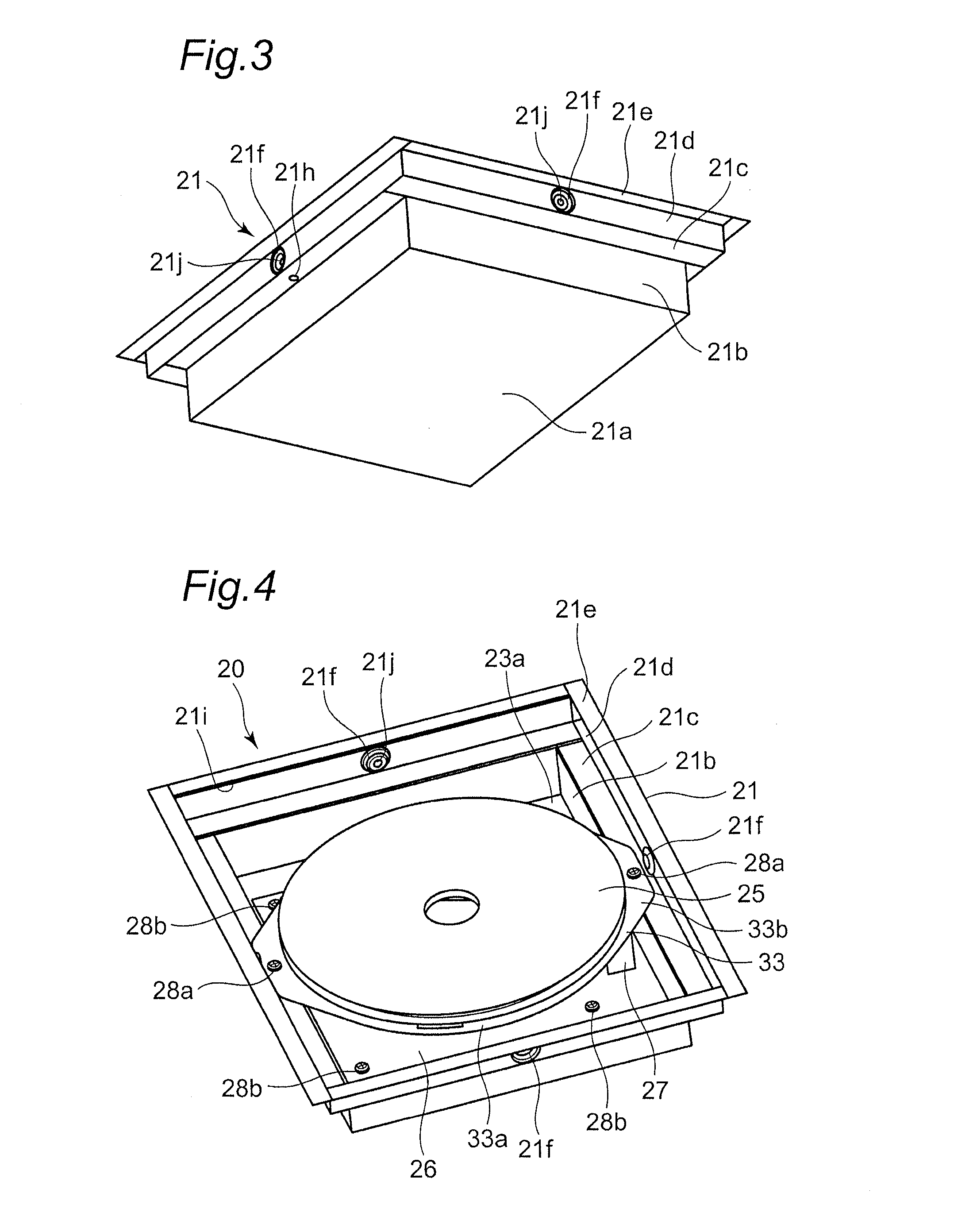
[0078]FIG. 1 is a perspective view showing a main body as the induction heating cooking device according to a first embodiment of the present disclosure. FIG. 2 is a perspective view looked at from the rear of a top plate unit of the induction heating cooking device according to the first embodiment. FIG. 3 is a perspective view looked at from below of the main body in the state that the top plate unit is detached in the induction heating cooking device according to the first embodiment. FIG. 4 is a perspective view looked at from above of the main body in the state that the top plate unit is detached in the induction heating cooking device according to the first embodiment.

[0079]As shown in FIG. 1, a main body 20 as the induction heating cooking device according to the first embodiment includes a framework 21 which has an approximately rectangular parallelepiped shape, and a top plate 22 which is provided on the framework 21 and on which a cooking container as an object to be heate...

second embodiment

[0104]Next, an induction heating cooking device according to a second embodiment of the present disclosure will be described with reference to appended FIGS. 8 to 12. FIG. 8 is a perspective view looked at from above of the main body of the induction heating cooking device according to the second embodiment of the present disclosure. FIG. 9 is a perspective view looked at from below of the main body of the induction heating cooking device according to the second embodiment. FIG. 10 is a perspective view looked at from above of the main body in the state that the top plate unit of the induction heating cooking device according to the second embodiment is detached. FIG. 11 is a perspective view showing a heating coil unit supporting member of the induction heating cooking device according to the second embodiment. FIG. 12 is a side sectional view showing the main body as the induction heating cooking device according to the second embodiment. In FIG. 8, the arrow F indicates the front...

third embodiment

[0125]Next, an induction heating cooking device according to a third embodiment of the present disclosure will be described with reference to appended FIGS. 13 and 14. FIG. 13 is a perspective view looked at from above of the state that the top plate unit is detached from the induction heating cooking device according to the third embodiment of the present disclosure. FIG. 14 is a side sectional view showing the induction heating cooking device according to the third embodiment.

[0126]In the following description of the third embodiment, because the basic configuration of the third embodiment is similar to the configuration of the above-mentioned first embodiment, description of similar points will not be repeated, and different points will be mainly described. Further, in the third embodiment, components that have functions and configurations similar to those of the first embodiment will be attached with the same symbols. A cooling configuration including the fan can be configured s...


PUM


Abstract

In order to provide an induction heating cooking device in which a supporting configuration of a heating coil unit is simple and can be easily assembled, and which can accurately and constantly maintain a distance between a top plate and heating coils, opposite side surfaces of a framework laid out below the top plate are configured to have first vertical parts, first horizontal parts, and second vertical parts. A heating coil supporting member that supports the heating coils is disposed to be bridged between the first horizontal parts of the opposite side surfaces of the framework, and the heating coil unit having the heating coil is configured to be securely supported by the first horizontal parts.

Description

TECHNICAL FIELD[0001]The present invention relates to an induction heating cooking device that is used for business or at standard homes, and relates more particularly to an installation configuration of a heating coil in the induction heating cooking device.BACKGROUND ART[0002]Conventionally, this type of an induction heating cooking device has had springs installed on components inside a main body, and has had a heating coil unit pressed against a top plate with the springs so that a distance between the heating coil and the top plate has been held (see Patent Literature 1 and Patent Literature 2, for example).[0003]FIG. 23 shows a side sectional view of a conventional induction heating cooking device described in Patent Literature 1 and Patent Literature 2. As shown in FIG. 23, the conventional induction heating cooking device is configured by a box body consisting of a top plate 101 on which a cooking container as an object to be heated is placed, a frame 102 that covers side su...

Claims


Application Information

Patent Timeline
Patent Type & Authority Applications(United States)
IPC IPC(8): H05B6/12
CPCH05B6/1209H05B6/1245H05B6/1254H05B6/1263H05B2206/022Y02B40/00H05B6/02H05B6/062
Inventor SUZUKI, HIDEKAZUTAKAHASHI, TOMOYAOGAWA, KENJIISAGO, HIROSHIANDO, SHUMPEIYOKONO, MASAHIRONAGATA, RYUUJIAIHARA, KATSUYUKIUSHIO, SHOZO
Owner PANASONIC INTELLECTUAL PROPERTY MANAGEMENT CO LTD
Why Eureka
Try Eureka