Drill chuck

Inactive Publication Date: 2015-04-30
ROHM GMBH & CO KG
View PDF4 Cites 10 Cited by
  • Summary
  • Abstract
  • Description
  • Claims
  • Application Information

AI Technical Summary

Benefits of technology

[0007]It is therefore object of the present invention

Problems solved by technology

Due to the locking device, which is essentially formed by the lock toothing assigned to the locking sleeve and by the mating toothing assigned to the chuck body, it is easily achieve

Method used


Image

  • Drill chuck
  • Drill chuck
  • Drill chuck

Examples


Example

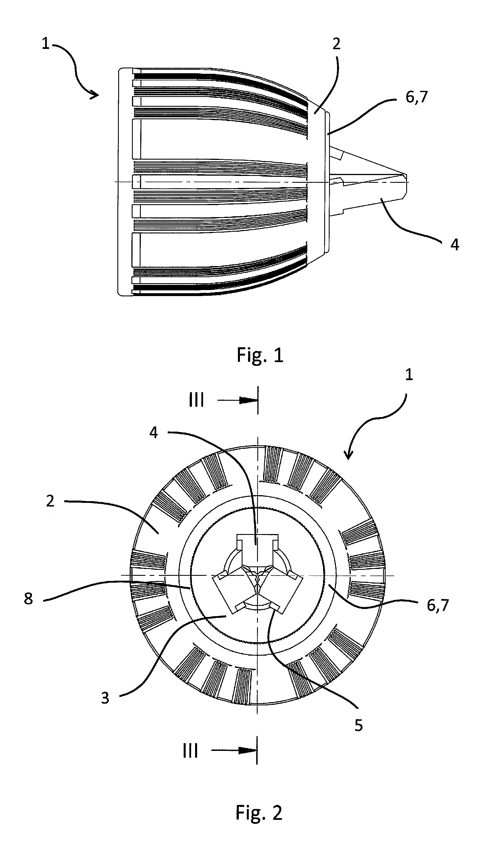
[0053]FIG. 1 shows a side view of a first specific embodiment of drill chuck 1 according to the invention. In addition to clamping sleeve 2, which surrounds a drill chuck 3 not illustrated in the drawing, FIG. 1 also shows clamping jaws 4, which are guided in guide receptacles 5 in chuck body 3. On the front side facing clamping jaws 4, clamping sleeve 2 is axially secured by a securing sleeve 7 having an annular band 6.

[0054]FIG. 2 shows a top view of the end of drill chuck 1 having clamping jaws 4. In addition to clamping sleeve 2, the top view illustrated in FIG. 2 shows, in particular, chuck body 3 and securing sleeve 7, which is pressed onto chuck body 3 with the aid of toothing 8 provided on the inner circumferential side and which axially secures clamping sleeve 2 with the aid of annular band 6. In addition, chuck body 3 is reinforced in the front part by securing sleeve 7.

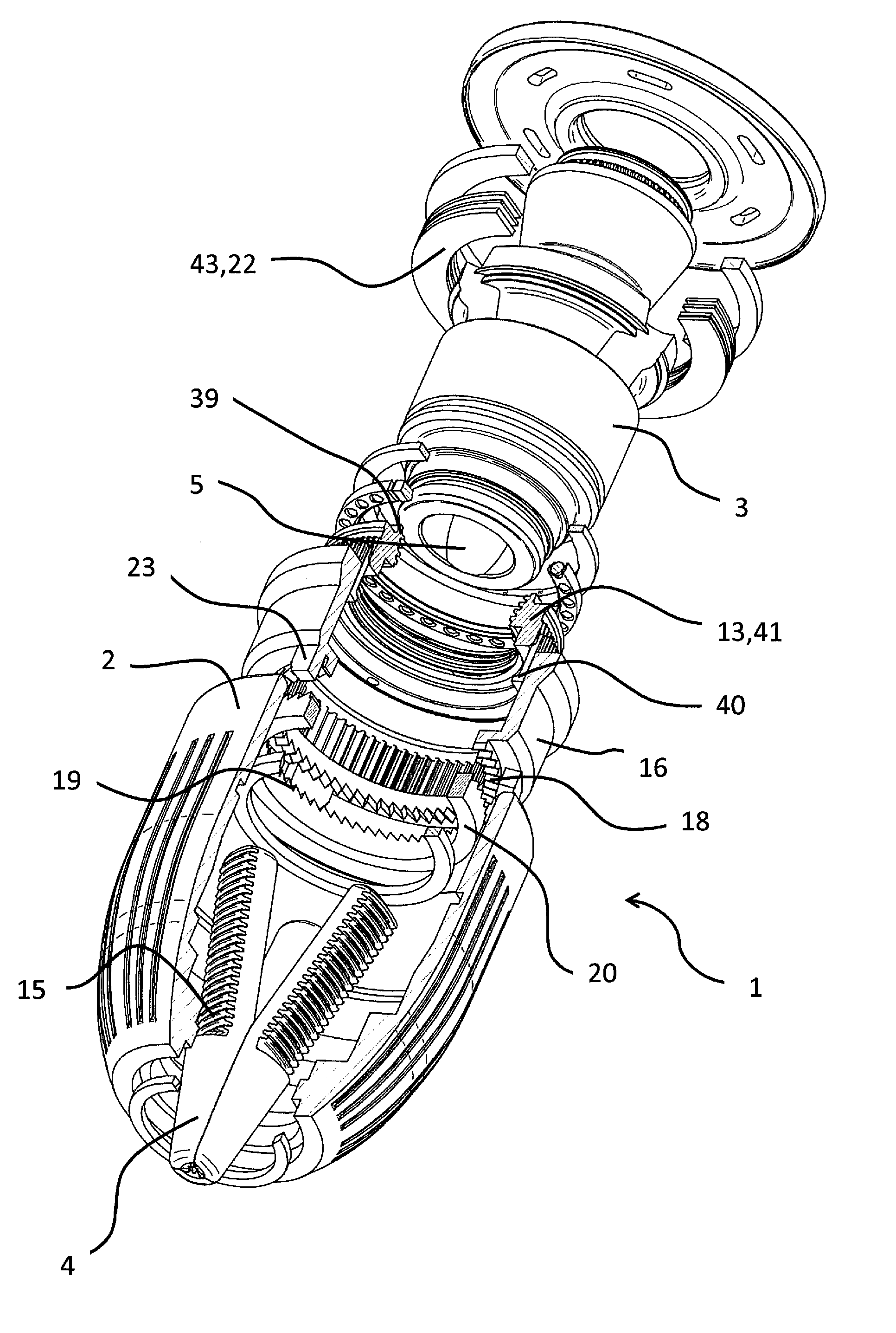
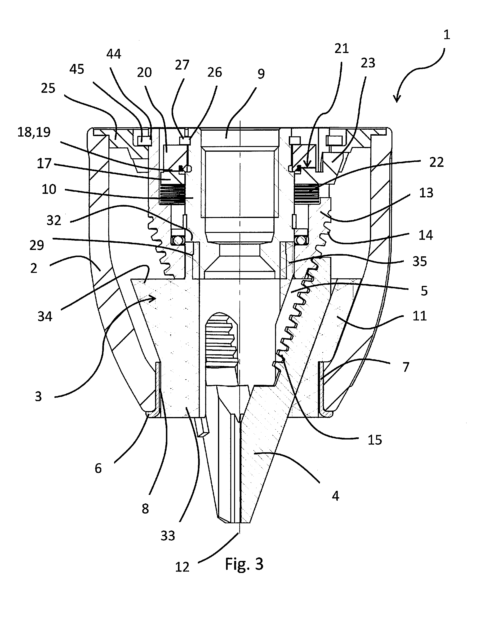
[0055]FIG. 3 shows, in a longitudinal section, a sectional view of the first specific embodiment along s...

Example

[0066]FIG. 19 shows a second specific embodiment of drill chuck 1 according to the invention, in which chuck body 3 is formed from a single piece. To adjust clamping jaws 4, which are guided in guide receptacles 5 of chuck body 3, threaded ring 13 is provided, which is in engagement with rows of teeth 15 provided on clamping jaws 4, with the aid of an inner thread 39. A toothed sleeve 40, which is rotatably fixedly coupled with locking sleeve 16, is disposed on the outer circumferential side of threaded ring 13. Locking sleeve 16 itself is axially movable on toothed sleeve 40. In the illustrated exemplary embodiment, control cams 23, upon which radial cams 24 provided on clamping sleeve 2 may act, are provided on locking sleeve 16. Once again, radial cams 24 are each delimited by engagement seats 28, which define the drilling configuration and the clamping configuration. Locking sleeve 16 may thus be axially adjusted against elastic restoring element 22, which is designed as a sinuo...

Example

[0068]A third specific embodiment of drill chuck 1 according to the invention is shown in the sectional view illustrated in FIG. 21.2 along section XXI-XXI from FIG. 20. The axial arrangement of mating toothing 19, which is assigned to toothed ring 20, and lock toothing 18, is reversed herein. However, the toothing engagement in the third specific embodiment, which is illustrated in FIG. 21.2, is slightly impaired, due to the axial clearance of clamping sleeve 2, since elastic restoring element 22 presses lock toothing 18 out of the toothing engagement in the drilling configuration.


PUM


Abstract

A drill chuck having a chuck body, on which a threaded ring is guided, which is in engagement with rows of teeth assigned to clamping jaws for the purpose of adjusting the clamping jaws having a thread and guided in the chuck body, as well as comprising a clamping sleeve which surrounds the chuck body and may be coupled with the threaded ring in a torque-transmitting manner and which may be coupled with the chuck body by a locking device. The locking device is formed by a locking sleeve, which has a lock toothing and is rotatably fixedly connected to the threaded ring and which is axially movable between a drilling configuration and a clamping configuration relative to the threaded ring and the clamping sleeve; the locking device is also formed by a mating toothing assigned to the chuck body.

Description

[0001]This nonprovisional application claims priority under 35 U.S.C. §119(a) to German Patent Application No. 10 2013 111 731.7, which was filed in Germany on Oct. 24, 2013, and which is herein incorporated by reference.BACKGROUND OF THE INVENTION[0002]1. Field of the Invention[0003]The invention relates to a drill chuck, comprising a chuck body on which a threaded ring is guided, which is in engagement with rows of teeth assigned to clamping jaws for the purpose of adjusting the clamping jaws guided in the chuck body and having a thread, as well as comprising a clamping sleeve which surrounds the chuck body and may be coupled with the threaded ring in a torque-transmitting manner and which may be coupled with the chuck body by a locking device.[0004]2. Description of the Background Art[0005]Drill chucks of this type, which have a locking device, are known from DE 198 32 891 A1, for example. In a first specific embodiment of the drill chuck illustrated in DE 198 32 891 A1, the lock...

Claims


Application Information

Patent Timeline
IPC IPC(8): B23B31/12
CPCB23B31/1253B23B31/123B23B31/1238B23B31/1246Y10T279/17615
Inventor SCHENK, PETERTHIEMANN, CHRISTIANHENGSBERGER, PATRICK
Owner ROHM GMBH & CO KG
Why Eureka
Try Eureka